
Novel flitch lifting platform structure of multi-wire cutting machine

A technology of multi-wire cutting machine and lifting table, which is applied in the direction of fine working devices, manufacturing tools, and working accessories, can solve the problems of reduced cutting efficiency, increased force on the cutting line, and reduced force on the cutting line, achieving Improve cutting efficiency, avoid wire breakage, and quickly adjust feed speed

Pending Publication Date: 2022-07-15
玉田县昌通电子有限公司
View PDF0 Cites 0 Cited by
  • Summary
  • Abstract
  • Description
  • Claims
  • Application Information

AI Technical Summary

Problems solved by technology

[0004] The feed of the existing multi-wire cutting machine lifting table is mostly set manually in sections. The feeding speed of the lifting table in each section is constant, and the cutting section of the workpiece is mostly changed. The cutting resistance and cutting resistance of the section are different. The cutting speed is different, which will cause the workpiece to be fed too fast when the cutting speed is reduced when the cross section of the workpiece is large, so that the force on the cutting line will increase. When the cross-section of the workpiece becomes smaller and the cutting speed increases, the feed of the workpiece is relatively slow, which reduces the force on the cutting line and cannot generate enough pressure, resulting in a decrease in cutting efficiency.
And because of the uneven force on the cutting line, the bending degree of the cutting line is inconsistent, resulting in uneven cutting marks on the cutting surface, reducing the cutting quality of the cutting product, and increasing the workload and difficulty of the subsequent process of cutting the product
[0005] Different materials and different cross-sections have different cutting speeds. The manual calculation of the feed speed can only be applied to relatively simple and regular cross-section shapes, but it cannot be calculated for complex and irregular cross-sections. It can only be set according to experience, and the error is large.

Method used


Image

  • Novel flitch lifting platform structure of multi-wire cutting machine
  • Novel flitch lifting platform structure of multi-wire cutting machine
  • Novel flitch lifting platform structure of multi-wire cutting machine

Examples


Embodiment Construction

[0024] The technical solutions in the present invention will be clearly and completely described below with reference to the embodiments and the accompanying drawings. Obviously, the described embodiments are only a part of the embodiments of the present invention, rather than all the embodiments. Based on the embodiments of the present invention, all other embodiments obtained by those of ordinary skill in the art without creative efforts shall fall within the protection scope of the present invention.

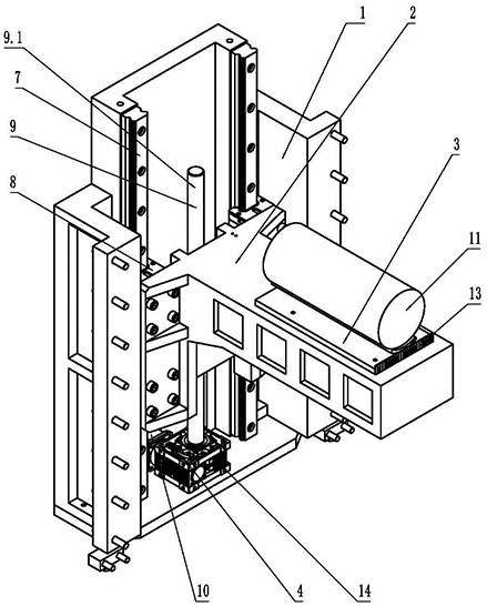
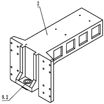
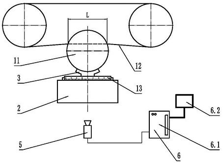
[0025] A new type of material plate lifting table structure for multi-wire cutting machine, such as Figure 1-3 As shown, including the base 1, the lifting table 2, the worktable 3, the feed drive assembly 4, the visual recognition assembly 5 and the upper computer 6, the base 1 is fixedly installed with two or more linear guide rails 7, two or two The linear guide rails 7 above are arranged in parallel with each other, and corresponding to each linear guide rail, two or more...


PUM


Abstract

The invention relates to the technical field of multi-wire cutting machines, in particular to a novel material plate lifting table structure of a multi-wire cutting machine, which comprises a base, a lifting table, a working table, a feeding driving assembly, a visual identification assembly and an upper computer, the visual identification assembly is installed on one side, perpendicular to the cutting section of a workpiece, of a cutting line of the multi-wire cutting machine, obtains an image of the workpiece cut by the cutting line and sends the image to the upper computer, the upper computer identifies and calculates the length of the cutting line in the workpiece when the workpiece is cut, and the length of the cutting line is adjusted according to the change of the length. The upper computer calculates the feeding speed of the lifting table and then sends an instruction to the motor to adjust the rotating speed of the motor, then the feeding speed of the lifting table is adjusted, the feeding speed does not need to be set manually, the feeding speed adjustment is rapid and accurate, the cutting efficiency is improved, the wire breaking fault caused by too large cutting wire pulling force is avoided, and the product quality is improved. And the cutting machine is suitable for cutting different materials and different sections.

Description

technical field [0001] The invention relates to the technical field of multi-wire cutting machines, in particular to a novel material plate lifting platform structure of the multi-wire cutting machine. Background technique [0002] At present, the widely used equipment for cutting various hard and brittle materials such as magnetic materials, crystals, ceramics, compounds, oxides, sapphire, and single crystal silicon is multi-wire cutting machine. Multi-wire cutting is a high-speed reciprocating motion through metal wires. A new type of cutting method that brings abrasives into the workpiece processing area for grinding and cuts hard and brittle materials into multiple slices at one time. Compared with other technologies, it has the advantages of high efficiency, high productivity, high precision and simple operation. [0003] When the multi-wire cutting machine is working, the cutting line is guided by more than a dozen wire wheels to form a net on the cutting roller assemb...

Claims


Application Information

Patent Timeline
Patent Type & Authority Applications(China)
IPC IPC(8): B28D7/04B28D7/00B28D5/04
CPCB28D5/0082B28D5/0058B28D5/045
Inventor 章博章雅冬刘素言
Owner 玉田县昌通电子有限公司
Learn More