Electrically operated valve

A technology of electric valves and spools, which is applied in the direction of valve lifts, valve details, valve devices, etc., and can solve problems such as large spool loads and suspense in the action of spools

Inactive Publication Date: 2016-09-14
SAGINOMIYA SEISAKUSHO INC
View PDF8 Cites 11 Cited by
  • Summary
  • Abstract
  • Description
  • Claims
  • Application Information

AI Technical Summary

Problems solved by technology

[0003] However, for electric valves with relatively large diameters, the thrust force on the screw thread generated by the torque of the magnet is relatively large due to the differential pressure. The load on the spool is large, and the operability of the spool is in doubt.

Method used


Image

  • Electrically operated valve
  • Electrically operated valve
  • Electrically operated valve

Examples


Embodiment Construction

[0036] Hereinafter, preferred embodiments (examples) of the present invention will be described with reference to the drawings.

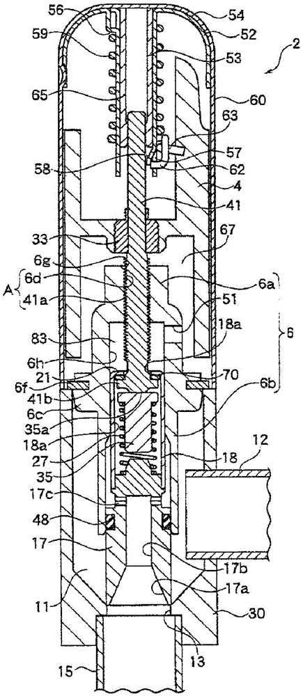
[0037] figure 1 It is a figure which shows the electric valve which is one Example of this invention.

[0038] In addition, in this specification, "upper" or "lower" is used in figure 1 specified in the state. That is, the rotor 4 is located above the spool 17 .

[0039] In this electric valve 2 , the valve main body 30 is integrally connected by welding or the like to the lower end portion on the opening side of the non-magnetic cylindrical cup-shaped housing 60 .

[0040] The valve main body 30 is a press-formed product produced by press working of a stainless steel plate, and has a valve chamber 11 inside. In the valve main body 30, the copper first pipe joint 12 directly communicated with the valve chamber 11 and the copper second pipe joint communicated with the valve chamber 11 through the valve port 13 are respectively fixedly installed...


PUM


Abstract

The present invention provides an electrically operated valve which can reduce the number of components and facilitate assembling and downsizing particularly when a back pressure chamber is arranged in a large-sized electrically operated valve. In the electrically driven valve, a screw joint (A) formed between an outer thread part (41) of which an outer peripheral surface is provided with an outer thread (41a) and an inner thread part (6a) on which an inner peripheral surface is provided with an inner thread (6d) turns rotational motion of the rotor (4) into linear motion and enables the valve element (17) to move linearly in the axial direction based on the linear motion. The electrically operated valve is characterized in that the inner thread part (6a) provided with the inner thread (6d) and a valve element guiding part (6b) that guides the valve element (17) to move in the axial direction are integrated into one member, and the valve element (17) is guided in the axial direction in such a way that the valve element (17) slidably contacts with the inner peripheral surface of the valve element guide member (6b).

Description

technical field [0001] The present invention relates to electric valves used in refrigeration cycles and the like. Background technique [0002] From the background of rationalization of control equipment such as consolidating a plurality of electric valves used for flow control into one, it is desired that the electric valves used in large-scale packaged air conditioners and refrigerators have a large diameter and a high pressure difference is generated. Also has good action performance. [0003] However, in an electric valve with a relatively large diameter, the thrust force of the screw thread generated by the torque of the magnet has a large load on the spool due to the differential pressure, and the operability of the spool is in doubt. [0004] So, for example, in Figure 4 In the conventional electric valve 1 shown, a sealing member 37 is interposed between the outer peripheral surface of a rod-shaped member (joint metal fitting 34) for lifting the valve element 31 w...

Claims


Application Information

Patent Timeline
Patent Type & Authority Applications(China)
IPC IPC(8): F16K31/04F16K27/02F16K1/36F16K1/32
CPCF16K1/32F16K1/36F16K27/02F16K31/04
Inventor 中川大树小林一也北见雄希
Owner SAGINOMIYA SEISAKUSHO INC
Why Eureka
Try Eureka