Communication circuit and communication method of electronic detonator

A communication circuit and electronic detonator technology, applied in electrical components, distribution line transmission systems, weapon accessories, etc., can solve the problems of occupying a lot of space, not suitable for transmitting high-frequency signals, and not suitable for small electronic detonators, etc. Low cost and small footprint

Active Publication Date: 2017-09-12
云南安爆数码电子科技有限公司
View PDF4 Cites 0 Cited by
  • Summary
  • Abstract
  • Description
  • Claims
  • Application Information

AI Technical Summary

Problems solved by technology

[0003] The invention provides a communication circuit for an electronic detonator, which adopts a power carrier communication method. The problem to be solved is that the M-BUS communication method used by the existing electronic detonator is not suitable for transmitting high-frequency signals, and the RS-485 communication method takes up less space. Many, technical problems that are not suitable for small electronic detonators

Method used


Image

  • Communication circuit and communication method of electronic detonator
  • Communication circuit and communication method of electronic detonator
  • Communication circuit and communication method of electronic detonator

Examples


Embodiment Construction

[0034] The principles and features of the present invention are described below in conjunction with the accompanying drawings, and the examples given are only used to explain the present invention, and are not intended to limit the scope of the present invention.

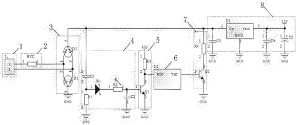
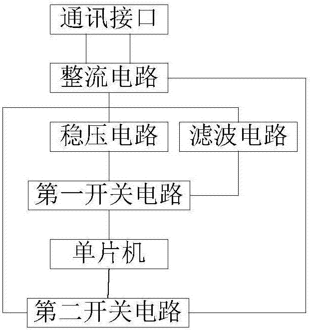
[0035] Such as figure 1 As shown, the first electronic detonator communication circuit provided by the embodiment of the present invention includes a communication interface, a filter circuit, a first switch circuit, a second switch circuit, a single-chip microcomputer, a rectifier circuit and a voltage stabilizing circuit.

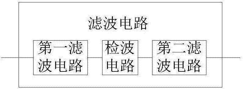
[0036] The communication interface is connected to the first input end and the second input end of the rectification circuit, and the first output end of the rectification circuit is respectively connected to the input end of the filter circuit, the input end of the voltage stabilizing circuit and the The input terminal of the second switch circuit is connected, the input terminal of the first ...


PUM


Abstract

The invention relates to a communication circuit and method of an electronic detonator. The communication circuit comprises a communication interface, a filtering circuit, a first switch circuit, a second switch circuit, a single-chip microcomputer, a rectifying circuit and a voltage stabilizing circuit; an exploder modulates carrier waves through a modulation signal; a carrier wave signal is generated and sent to the communication circuit of the electronic detonator through a bus; the communication circuit demodulates the carrier wave signal and performs treatment; then a signal is sent to the exploder; and the communication process is completed. According to the communication circuit and method of the electronic detonator, communication is performed by means of a power line network, rewiring is not needed, the beneficial effects that the occupied space is small and the constructing and running cost is low are achieved, and transmission of a high-frequency signal and a lower-frequency signal is supported at the same time.

Description

technical field [0001] The invention relates to the technical field of electronic detonators, in particular to a communication circuit and a communication method for electronic detonators. Background technique [0002] The existing communication methods of electronic detonators mainly use M-BUS, RS-485, etc., but M-BUS is suitable for the transmission of low-frequency signals, and is prone to deformation when used to transmit high-frequency signals. RS-485 requires a dedicated Lines take up a lot of space and are not suitable for small electronic detonators. Contents of the invention [0003] The invention provides a communication circuit for an electronic detonator, which adopts a power carrier communication method. The problem to be solved is that the M-BUS communication method used by the existing electronic detonator is not suitable for transmitting high-frequency signals, and the RS-485 communication method takes up less space. Many, not applicable to the technical p...

Claims


Application Information

Patent Timeline
Patent Type & Authority Patents(China)
IPC IPC(8): F42C19/12H04B3/54
CPCF42C19/12H04B3/546
Inventor 李泽雄王中华管圣文陈锐填敬光慈
Owner 云南安爆数码电子科技有限公司
Why Eureka
Try Eureka