
Power supply circuit of electric sewing machine

A technology for electric sewing machines and power circuits, which is applied in the direction of high-efficiency power electronic conversion, electrical components, and adjustment of electric variables, etc., which can solve problems such as difficulty in using feet, increased power consumption of electric sewing machines, and increased use costs of electric sewing machines. Effects of power loss and cost reduction

Inactive Publication Date: 2016-09-14
浙江逸达科技有限公司
View PDF11 Cites 0 Cited by
  • Summary
  • Abstract
  • Description
  • Claims
  • Application Information

AI Technical Summary

Problems solved by technology

[0003] Existing sewing machines are mainly divided into foot-operated and electric. The foot-operated is provided with a foot-operated pedal below, and then a runner is set on one side of the pedal. The pedal drives the runner through a link mechanism, and then turns The wheel and the rotating wheel on the sewing machine are connected by a belt, so as to realize the effect of driving the sewing machine by the foot, but the foot-operated sewing machine will have a large volume, and secondly, after a long time of use, people's feet will be very tired. Therefore, compared with the electric sewing machine, foot operation is much more difficult to use, and the existing electric sewing machine only modifies the original foot-operated driving mechanism to be driven by a motor, which avoids the problems of large size and tired feet of the foot-operated sewing machine. In order to be able to supply power to the driver and the motor well, the existing electric sewing machine needs to set up a power supply circuit for power supply, and the existing power supply circuit converts the external mains alternating current into direct current, drives the motor through the direct current, and then After stepping down the DC power through the step-down circuit, it will be sent to each chip in the driver to drive the motor to operate better. The existing step-down circuit method is realized by connecting multiple resistors in series on the DC circuit. In this way, the resistance will consume a lot of power during the step-down process, which will lead to an increase in the power consumption of the electric sewing machine and increase the use cost of the electric sewing machine

Method used


Image

  • Power supply circuit of electric sewing machine
  • Power supply circuit of electric sewing machine

Examples


specific Embodiment approach

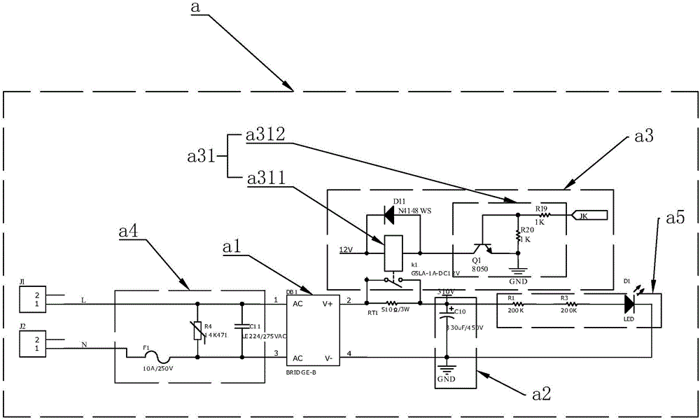
[0038] As an improved specific implementation manner, the short-circuit circuit a31 includes:

[0039] A short-circuit relay a311, the short-circuit relay a311 has a switch part and an electromagnetic part, the switch part is connected in parallel with the anti-shock resistance RT1, and the electromagnetic part controls the opening and closing of the switch part;

[0040] A driving circuit a312, the driving circuit a312 is coupled to the short-circuit relay a311 to provide an action signal to the electromagnetic part of the short-circuit relay a311, and the driving circuit a312 includes:

[0041]Switching transistor Q1, the base of the switching transistor Q1 is coupled with a resistor and then coupled to the control chip of the driver, the emitter is grounded, the emitter is also coupled with a resistor and then coupled to the base, and the collector is coupled to the short circuit relay a311 The electromagnetic part is then coupled to the power supply. Through the setting of...


PUM


Abstract

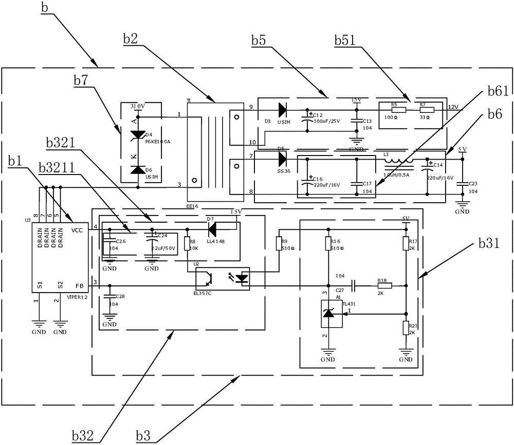
The invention discloses a power supply circuit of an electric sewing machine. The power supply circuit comprises a rectifying circuit and a switch power supply circuit, wherein the rectifying circuit has an input end and an output end; the input end is coupled to an external mains supply while the output end outputs a direct current power supply; the switch power supply circuit has an input end and an output end; and the input end is coupled to the output end of the rectifying circuit so as to modulate the direct current power supply at the output end of the rectifying circuit and then to output a low voltage power supply. According to the power supply circuit of the electric sewing machine, the alternating current of the external mains supply can be converted into direct current effectively due to the rectifying circuit; and meanwhile, due to the switch power supply circuit, an effect of carrying out voltage drop processing on the direct current and then outputting the processed direct current to the each chip of the drive so as to supply power to each chip can be effectively realized.

Description

technical field [0001] The invention relates to an electric sewing machine, and more specifically relates to a power supply circuit of the electric sewing machine. Background technique [0002] Sewing machines are widely used in the field of textile and clothing. They play a very important role in sewing clothes. Through the use of sewing machines, the sewing efficiency of clothes can be greatly improved, and the work efficiency of workers can be improved. The mending work saves a lot of time. [0003] Existing sewing machines are mainly divided into foot-operated and electric. The foot-operated is provided with a foot-operated pedal below, and then a runner is set on one side of the pedal. The pedal drives the runner through a link mechanism, and then turns The wheel and the rotating wheel on the sewing machine are connected by a belt, so as to realize the effect of driving the sewing machine by the foot, but the foot-operated sewing machine will have a large volume, and s...

Claims


Application Information

Patent Timeline
IPC IPC(8): H02M7/04H02M3/335H02M1/092
CPCH02M1/092H02M3/33523H02M7/04H02M1/0048H02M1/007Y02B70/10
Inventor 王晓东
Owner 浙江逸达科技有限公司
Learn More