
LED driving device and its control circuit and control method

A technology of LED drive and control circuit, applied in lighting devices, electric light sources, electrical components, etc., can solve the problems of complex control and high cost, and achieve the effect of good input voltage linearity, high power factor, and cost reduction

Active Publication Date: 2018-11-30
HANGZHOU SILAN MICROELECTRONICS
View PDF7 Cites 0 Cited by
  • Summary
  • Abstract
  • Description
  • Claims
  • Application Information

AI Technical Summary

Problems solved by technology

[0008] The technical problem to be solved by the present invention is to provide a new type of LED drive device and its control circuit and control method to overcome the shortcomings of the existing LED drive control circuit, such as high cost, complicated control and dimming with thyristor

Method used


Image

  • LED driving device and its control circuit and control method
  • LED driving device and its control circuit and control method
  • LED driving device and its control circuit and control method

Examples


Embodiment Construction

[0038] Various embodiments of the invention will be described in more detail below with reference to the accompanying drawings. In the various drawings, the same elements are denoted by the same or similar reference numerals. For the sake of clarity, various parts in the drawings have not been drawn to scale.

[0039] The present invention will be further described below in conjunction with the accompanying drawings and embodiments.

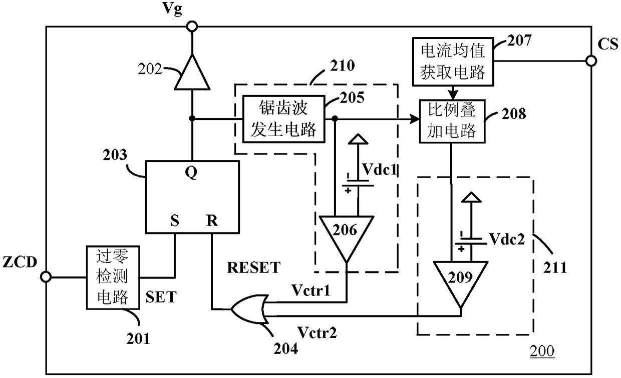
[0040] refer to figure 2 According to the embodiment of the present invention, the LED drive control circuit 200 includes a current average acquisition circuit 207, a proportional superposition circuit 208, a conduction time control circuit 210, a comparison circuit 211, an OR gate 204, an RS trigger circuit 203, a switch drive circuit 202, an overlay Zero detection circuit 201. The LED driving control circuit 200 may have a separate reference ground.

[0041] The on-time control circuit 210 includes a sawtooth wave generating circuit 205 , ...


PUM


Abstract

The application discloses an LED driving device, a control circuit and a control method thereof. The LED drive control circuit includes: a conduction time control circuit, used to generate a first control signal according to the sawtooth wave signal and the first reference voltage; a current average value acquisition circuit, used to generate an average current reflecting the average value of the output current according to the current sampling signal signal; a proportional superposition circuit for superimposing the average current signal and the sawtooth wave signal in proportion to generate a superposition signal; a comparison circuit for comparing the superposition signal with a second reference voltage to generate a second control signal ; an OR gate, used to generate a reset signal according to the first control signal and the second control signal; a set signal generating circuit, used to generate a set signal; and an RS flip-flop, used to generate a reset signal according to the reset signal and The set signal generates a switch control signal. The LED drive control circuit can omit the compensation network of the regulation loop, realize high power factor, and does not need a discharge circuit when it is applied to the dimming of silicon controlled rectifiers.

Description

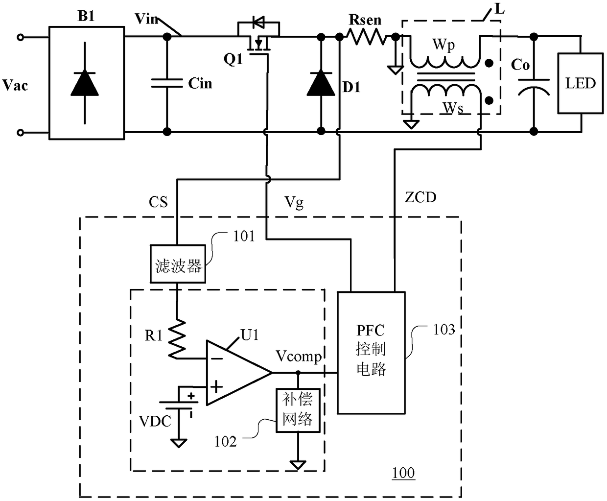
technical field [0001] The invention relates to an LED driving device, a control circuit and a control method thereof. Background technique [0002] As we all know, LED is a current mode device. In order to keep the luminous flux output by the LED constant, the prior art generally adopts a closed-loop control control circuit to realize the constant output current of the LED driving device. In addition, in order to reduce the harmonic pollution of the drive device to the grid, the control circuit also needs to achieve a high power factor. [0003] figure 1 Shown is a simplified schematic diagram of a prior art LED drive control circuit. figure 1 The circuit shown is a floating buck type high power factor LED driver. Such as figure 1 As shown, the input AC voltage Vac is rectified by the rectifier bridge B1 and filtered by the capacitor Cin to obtain a rectified bus voltage Vin. The bus voltage Vin is a half-sine wave signal. The LED drive control circuit 100 includes a...

Claims


Application Information

Patent Timeline
Patent Type & Authority Patents(China)
IPC IPC(8): H05B33/08H05B44/00H05B45/30
CPCH05B45/40H05B45/37H05B45/10
Inventor 谢小高陈华捷
Owner HANGZHOU SILAN MICROELECTRONICS
Learn More