A system for adaptive optics imaging of micro blood vessels in the retinal inner nucleus

A technology of adaptive optics and inner core layer, which is applied in the fields of application, medical science, and eye testing equipment, etc. It can solve the problems of different focal lengths and structural parameters of the human eye, and the difficulty of capturing the image plane of micro blood vessels in the inner core layer, etc.

Active Publication Date: 2017-07-14
CHANGCHUN INST OF OPTICS FINE MECHANICS & PHYSICS CHINESE ACAD OF SCI
View PDF10 Cites 0 Cited by
  • Summary
  • Abstract
  • Description
  • Claims
  • Application Information

AI Technical Summary

Problems solved by technology

The purpose of this invention is to solve the problem that the focal length and structural parameters of the human eye are different, and it is difficult to capture the microvascular image plane of the inner core layer, so that the patient's eyes are only irradiated with visible light shorter than 18ms in one test, and the adaptive image can be completed. Clear imaging of tiny blood vessels after difference correction

Method used


Image

  • A system for adaptive optics imaging of micro blood vessels in the retinal inner nucleus
  • A system for adaptive optics imaging of micro blood vessels in the retinal inner nucleus
  • A system for adaptive optics imaging of micro blood vessels in the retinal inner nucleus

Examples


Embodiment Construction

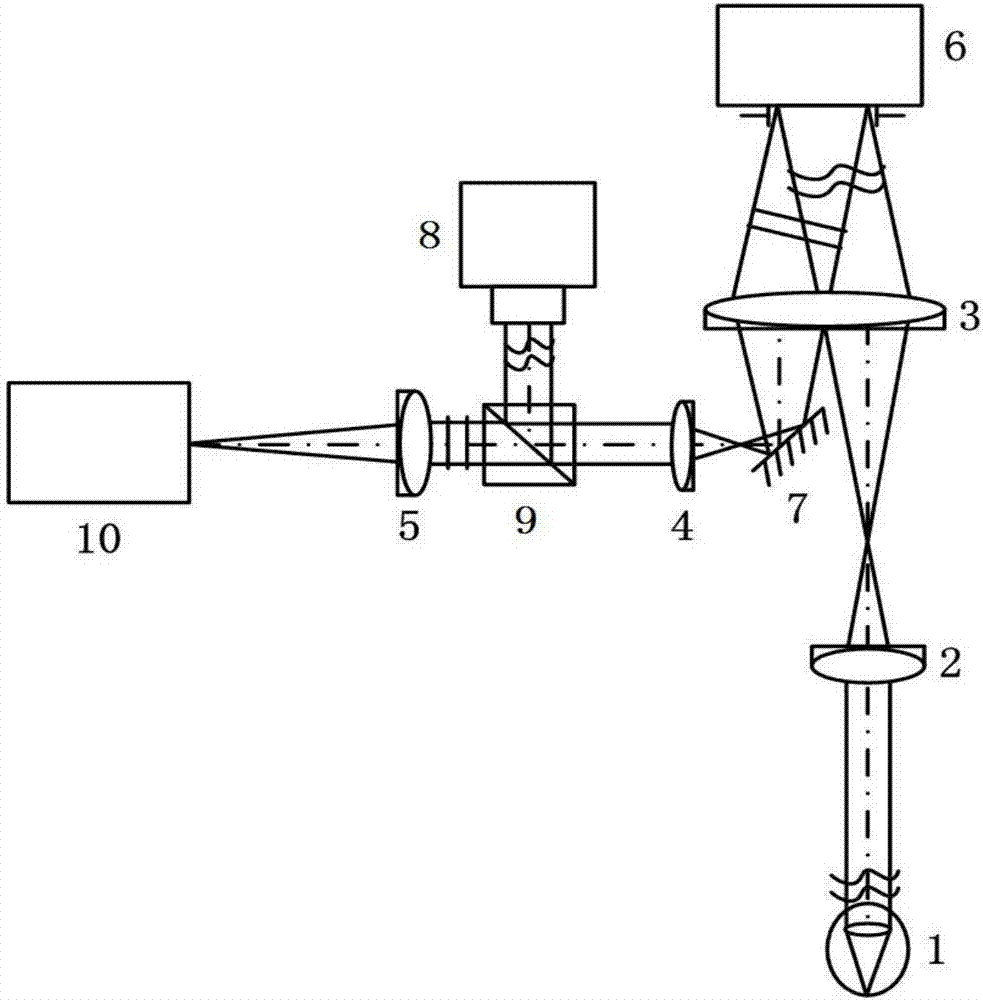
[0028] 1. Use as figure 1 The shown fundus adaptive optics imaging system based on liquid crystal wavefront corrector is configured with fundus illumination light source, visual mark, one-dimensional electronically controlled displacement stage and a computer. The characteristic parameters of each device are as follows:

[0029] (1) Fundus illumination light source: In order to simplify the verification experiment, a monochromatic light source with a wavelength of 808nm was selected as the imaging light source for the micro-vessels in the inner core layer, because the micro-vessels can also be imaged at a wavelength of 808nm, but the imaging contrast is relatively high compared to the yellow-green light source in the visible light band. Low, it is possible as a technical verification; because the visual target is all visible light, the wavelength of the visual target in this embodiment is 500nm, the wavelength of the imaging light source, the aberration detection light source a...


PUM


Abstract

The invention relates to a high-definition imaging system for rapid capture of retinal microvessels with a diameter below 10 microns and adaptive aberration correction in the optical imaging technology for adaptive correction of eye wave aberration. As shown in the figure: the surface of the visual cell layer is used as the reference position along the optical axis; the distance between the public area of ​​the inner core layer of a large number of human microvessels and the center plane of the public area relative to the reference position is calculated; the human eye is equivalent to a lens, and the current The human eye optical model simulates the relationship between the effective focal length of the human eye and the axial length of the human eye; the measured axial length of the human eye is substituted into the relationship between the effective focal length of the human eye and the axial length of the human eye to calculate the effective focal length of the human eye; Finally, according to the optical parameters of the adaptive optics imaging light path, the image plane position of the central plane of the common area of ​​the inner core layer is calculated, and the imaging camera is set here so that the eyes of the patient under inspection are only irradiated with visible light shorter than 18ms during one inspection, that is, It can complete the clear imaging of micro blood vessels in the inner core layer with a diameter of about 10 μm.

Description

technical field [0001] The invention belongs to the technical field of fundus microscopic imaging, and relates to a method for rapid capture of microvascular layers and high-definition imaging of adaptive aberration correction in the optical imaging technology of adaptive correction of eye wave aberration, in particular to a method without contrast agent A system for adaptive optics imaging of retinal microvessels with a diameter of less than 10 microns. Background technique [0002] The eyeball is a complex optical system with a self-adjusting function and may move subconsciously at any time. The structure of the human eye can be compared to the optical structure of a camera. The lens of a camera is composed of the cornea, lens, anterior and posterior chambers, vitreous body, and ciliary body for focusing. The photodetector of the camera is the retina of the human eye fundus. on the visual cells. The retina is a 10-layer translucent tissue structure, and the visual cells ...

Claims


Application Information

Patent Timeline
Patent Type & Authority Patents(China)
IPC IPC(8): A61B3/12A61B3/14
CPCA61B3/1015A61B3/12A61B3/14
Inventor 宣丽李大禹王少鑫张佩光曹召良穆全全杨程亮姚丽双刘永刚彭增辉徐焕宇张杏云王启东王玉坤杨乐宝
Owner CHANGCHUN INST OF OPTICS FINE MECHANICS & PHYSICS CHINESE ACAD OF SCI
Why Eureka
Try Eureka