Perforating device

A technology of punching device and drilling mechanism, applied in positioning device, drilling/drilling equipment, clamping and other directions, can solve problems such as low production efficiency, poor safety, and debris splashing

Inactive Publication Date: 2016-09-21
YINFENG CASTING WUHU CO LTD
View PDF6 Cites 15 Cited by
  • Summary
  • Abstract
  • Description
  • Claims
  • Application Information

AI Technical Summary

Problems solved by technology

[0004] In view of the above-mentioned prior art, the object of the present invention is to overcome the inconvenient drill bit replacement of the punching device in the prior art. Moreover, during the use of the punching device, a large amount of debris can be produced. The punching device in the prior art does not have a corresponding debris handling structure, and the generated debris splashes everywhere, which not only increases th...

Method used


Image

  • Perforating device
  • Perforating device
  • Perforating device

Examples


Embodiment Construction

[0028] Specific embodiments of the present invention will be described in detail below in conjunction with the accompanying drawings. It should be understood that the specific embodiments described here are only used to illustrate and explain the present invention, and are not intended to limit the present invention.

[0029] In the invention, in the absence of a contrary statement, "up, down" and other orientation words included in the term only represent the orientation of the term in the normal use state, or the common name understood by those skilled in the art, rather than should be considered a limitation of the term.

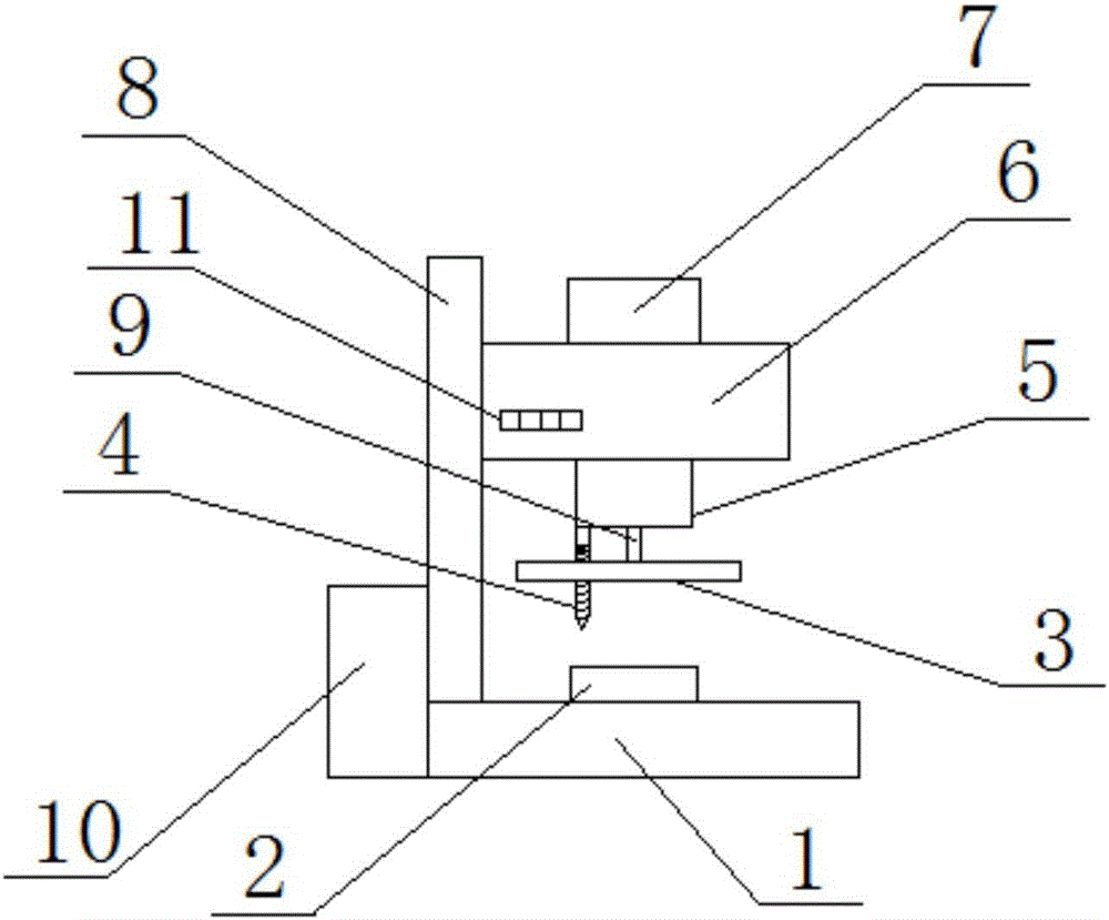
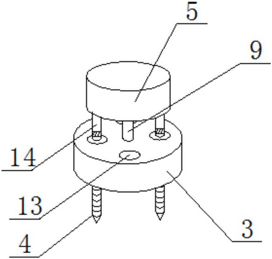
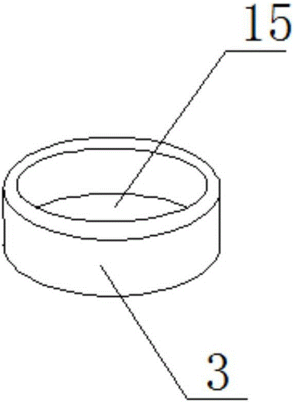
[0030] Such as figure 1 , the present invention provides a drilling device, the drilling device includes: a workbench 1, a drilling mechanism, a support rod 8, a drill storage platform 5, a telescopic rod 14, a drill 4, a lifting rod 9 and a protective cover 3, The support rod 8 is vertically arranged on the upper surface of the workbench 1, the drillin...


PUM


Abstract

The invention discloses a perforating device. The perforating device comprises a workbench, a drilling mechanism, a supporting rod, a drill bit storage platform, telescopic rods, drill bits, lifting rods and a protection cover. The supporting rod is vertically arranged on the upper surface of the workbench. The drilling mechanism is arranged on the supporting rod. The upper end of the drill bit storage platform is connected with the drilling mechanism, and the lower end of the drill bit storage platform is partially concaved inwards to form containing grooves matched with the drill bits. One end of each telescopic rod is fixed in the corresponding containing groove, and the other end of each telescopic rod is connected with the corresponding drill bit. The drilling mechanism is provided with a control switch which can separately control expansion, contraction and rotation of the multiple telescopic rods. The protection cover is arranged below the drill bit storage platform. One end of each lifting rod is connected with the drill bit storage platform, and the other end of each lifting rod is connected with the protection cover. The protection cover is provided with through holes matched with the drill bits in the vertical direction. According to the perforating device, the problems that drill bit replacement of a perforating device in the prior art is inconvenient, and a certain threat is posed to the safety of a user due to the fact that a corresponding chip processing mechanism is not arranged, and produced chips splash everywhere are solved.

Description

technical field [0001] The invention relates to the field of mechanical manufacturing equipment, in particular to a punching device. Background technique [0002] Punching device refers to the general name of machinery and equipment that leaves cylindrical holes or holes on the target by means of rotary cutting or rotary extrusion with a tool that is harder and sharper than the target. It plays a very important role in industrial production. important role, but it is inconvenient to replace the drill bit in the punching device in the prior art. It is necessary to disassemble the original drill bit and replace the required drill bit. In the process, a large amount of debris will be generated. The punching device in the prior art does not have a corresponding debris processing mechanism, and the debris generated splashes around, which not only increases the cleaning workload of the user, but also has poor safety and is harmful to the user. security poses certain threats. [...

Claims


Application Information

Patent Timeline
IPC IPC(8): B23B47/26B23Q11/08B23Q3/157
CPCB23B47/26B23Q3/157B23Q11/08
Inventor 刘同顺唐加阁汪俊华郑浩
Owner YINFENG CASTING WUHU CO LTD
Why Eureka
Try Eureka