Multi-angle polishing machine

A grinding machine and multi-angle technology, applied in the grinding field, can solve the problems of high labor intensity, low production efficiency, cumbersome angle adjustment, etc., and achieve the effects of improving work efficiency, convenient operation, and simple use

Inactive Publication Date: 2017-11-03
SUZHOU BIAOGAN INTPROP OPERATION CO LTD
View PDF6 Cites 3 Cited by
  • Summary
  • Abstract
  • Description
  • Claims
  • Application Information

AI Technical Summary

Problems solved by technology

[0002] With the improvement of industrial level, plastic pipes are often used in various manufacturing processes, and in different manufacturing processes, plastic pipe fittings need to be polished after cutting before they can be used. In the past, manual control of pipe fittings was generally used. Grinding and polishing at an angle is labor-intensive, time-consuming and labor-intensive, and the production efficiency is low
[0003] Although there are automatic grinding machines in the current market, the relative structure is relatively complicated. For example, the patent application publication number 201620382817.4 discloses a multi-angle grinding machine for plastic pipe fittings. The vertical movement of the grinding wheel is realized by the rotation of the adjustment device. , horizontal movement and rotation effects, speeding up production efficiency
[0004] Judging from the prior art published by the invention, the effect is not very satisfactory, the grinding machine is not easy to carry, the scraps and powder generated during grinding are easy to splash and accidentally injure the staff, the safety is not high, and the angle adjustment is somewhat cumbersome

Method used


Image

  • Multi-angle polishing machine
  • Multi-angle polishing machine

Examples


Embodiment Construction

[0016] The technical solutions in the embodiments of the present invention will be clearly and completely described below in conjunction with the accompanying drawings in the embodiments of the present invention. Obviously, the described embodiments are only a part of the embodiments of the present invention, rather than all the embodiments. Based on the embodiments of the present invention, all other embodiments obtained by those of ordinary skill in the art without creative work shall fall within the protection scope of the present invention.

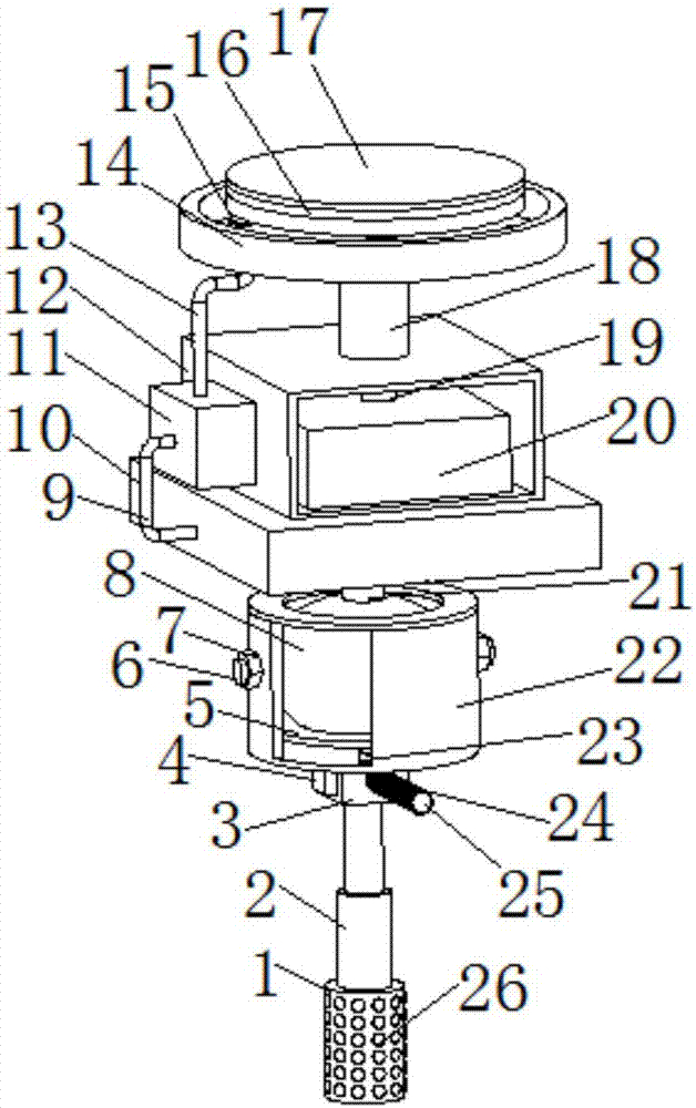
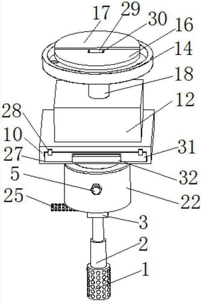
[0017] See Figure 1-2 , The present invention provides a technical solution: a multi-angle grinder comprising a handle 1, a telescopic rod 2 is provided at the top of the handle 1, a support block 3 is provided at the telescopic end of the telescopic rod 2, and the left side of the support block 3 is provided There is a control switch 4, the front side of the support block 3 is provided with a handle 25, the side of the handle 1 is prov...


PUM


Abstract

The invention discloses a multi-angle polishing machine comprising a handle. The top end of the handle is provided with a telescopic rod. A supporting block is arranged at the telescopic end of the telescopic rod. The left side face of the supporting block is provided with a control switch. A hand shank is arranged on the front side face of the supporting block. The upper surface of the supporting block is provided with a steering box. A steering ball is arranged in the steering box. The surface, protruding out of the steering box, of the steering ball is provided with a supporting column. A storage box is arranged at the top end of the supporting column. The upper surface of the storage box is provided with a motor box. The upper surface of the motor box is provided with a fixing cylinder. The multi-angle polishing machine is simple in structure and convenient to operate. Waste chips can be effectively prevented from splashing during polishing through a suction storage groove. Powder and the waste chips generated during polishing are collected through a dust collection machine. Workers can be effectively protected. The angle of the polishing machine can be easily adjusted through the steering box. Through cooperation between the handle and the hand shank, the polishing machine is convenient to carry, and use is easier. Through a replaceable polishing head, cost is reduced, and therefore the work efficiency is further improved.

Description

Technical field [0001] The present invention relates to the technical field of polishing, in particular to a multi-angle polishing machine. Background technique [0002] With the improvement of the industrial level, plastic pipes are often used in various manufacturing processes. In different manufacturing processes, plastic pipe fittings need to be polished before they can be used. In the past, manual control of pipe fittings is generally used. The angle is polished, which is labor-intensive, time-consuming and labor-intensive, and the production efficiency is low. [0003] Although there are automatic grinding machines in the current market, the relative structure is relatively complicated. For example, the patent application publication number 201620382817.4 discloses a multi-angle grinding machine for plastic pipe fittings. The vertical movement of the grinding wheel is realized by the rotation of the adjusting device. The effect of horizontal movement and rotation speeds up p...

Claims


Application Information

Patent Timeline
Patent Type & Authority Applications(China)
IPC IPC(8): B24B23/02B24B41/00B24B55/05B24B55/10
Inventor 孙生强
Owner SUZHOU BIAOGAN INTPROP OPERATION CO LTD
Why Eureka
Try Eureka