
Machining process for flow spoiler bands

A processing technology and a technology of turbulence zone, applied in the field of heat exchanger equipment, can solve the problems of uneven heat exchange, broken sheets, waste products, etc., and achieve the effects of improving cooling effect, large contact area, and increased surface area

Inactive Publication Date: 2016-09-21
CHONGQING YUQING MACHINERY MFR
View PDF6 Cites 8 Cited by
  • Summary
  • Abstract
  • Description
  • Claims
  • Application Information

AI Technical Summary

Problems solved by technology

[0004] The disadvantages of this spiral bond processing technology are: 1. When the rotary stretching device is driven to rotate, the pitch of the sheet is affected by factors such as the rotating speed of the rotary stretching device, the number of revolutions, and the conveying speed of the sheet, and the final spiral bond is formed. Several screw pitches (equivalent to the turbulence unit referred to below) are not exactly the same. After such helical ties are installed in the tube bundle, the fluid at different positions in the tube bundle will receive different turbulence, resulting in uneven heat transfer; or rotation stretching The device setting is unreasonable, and the sheet will be twisted when there are too many turns; 2. When cutting the spiral bond, the automatic cutting machine feeds the cutter along the cross-sectional direction of the spiral bond, and the cutter is easy to destroy the spiral shape of the spiral bond, resulting in waste product

Method used


Image

  • Machining process for flow spoiler bands
  • Machining process for flow spoiler bands
  • Machining process for flow spoiler bands

Examples


Embodiment Construction

[0020] The present invention will be described in further detail below by means of specific embodiments:

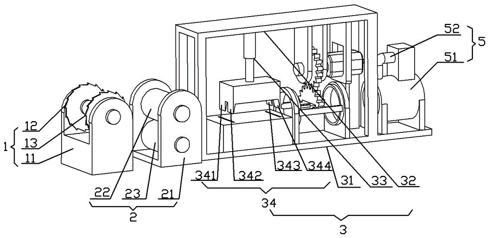
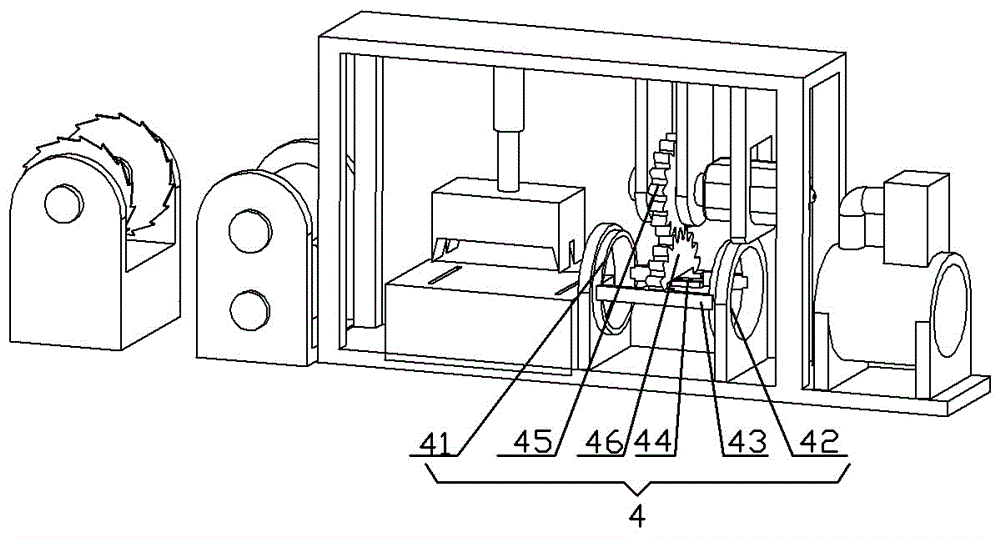
[0021] The reference signs in the accompanying drawings of the specification include: trimming mechanism 1, first base 11, first cutting wheel 12, second cutting wheel 13; heat treatment mechanism 2, second base 21, upper heat conducting roller 22, lower heat conducting roller 23 ; Prefabricated line cutting mechanism 3, the third base 31, beam 32, telescopic cylinder 33, prefabricated line cutting knife 34, the first cutting knife 341, the second cutting knife 342, the third cutting knife 343, the fourth Cutter 344; Torsion mechanism 4, left rotating ring 41, right rotating ring 42, clamping block 43, groove 44, driving gear 45, driven gear 46; air cooling mechanism 5, air cooling pipe 51, communication Pipe 52, prefabricated line A, spoiler unit B.

[0022] The equipment used in the spoiler belt processing technology is basically as attached figure 1 , figure 2 Show...


PUM


Abstract

The invention belongs to the technical field of heat exchanger equipment and relates to a machining process for flow spoiler bands. The machining process comprises the steps of edge cutting treatment, preheating treatment, sheet material prewire crush-cutting, twisting treatment, reversed twisting treatment, air-cooling sizing and final trimming. Firstly, prewires are adopted for the machining process to standardize the length of flow spoiler units, the flow spoiler units of a finished flow spoiler band are the same in length, the turbulent flow force on fluid in different positions in a tube bundle is the same after the flow spoiler band is mounted in the tube bundle, and heat exchanging is more even; secondly, according to the scheme, a conventional rotary stretching device is omitted so that the situation that a sheet material is twisted off due to a conventional rotary stretching method is avoided; and thirdly, due to the fact that a cross section is formed in the process of sheet material prewire crush-cutting, the overall superficial area of the sheet material is increased, the contact area between the molded flow spoiler band and cold air is larger when the molded flow spoiler band passes by an air cooling mechanism, and the cooling effect of the flow spoiler band is improved.

Description

technical field [0001] The invention belongs to the technical field of heat exchanger equipment. Background technique [0002] Tube heat exchanger, which is the most typical partition heat exchanger, has a long history of industrial application, and still occupies a dominant position in all heat exchangers. The tubular heat exchanger is mainly composed of a shell, a tube bundle, a tube plate and a head. The shell is mostly circular, and there are parallel tube bundles inside, and the two ends of the tube bundle are fixed on the end plate. There are spiral ties (also known as twisted iron, spoiler belt, spiral flat steel, etc.) in the rotating connection in the tube bundle, and the spiral ties are mainly used to improve heat exchange efficiency. When the fluid enters the heat exchange tube, the spiral bond makes the fluid enter a turbulent state, breaks the stagnant layer of the tube wall, increases the contact area between the fluid and the tube wall of the heat exchange tu...

Claims


Application Information

Patent Timeline
IPC IPC(8): B23P15/00
CPCB23P15/00
Inventor 谭勇
Owner CHONGQING YUQING MACHINERY MFR
Learn More