Wheel hub motor electric car braking system and braking energy recovery control method

A hub motor and braking system technology, applied in electric braking systems, electric vehicles, control devices, etc., can solve problems such as expensive, excessive feedback current, and battery damage

Active Publication Date: 2016-09-21
福建艾密克新能源科技有限公司
View PDF5 Cites 20 Cited by
  • Summary
  • Abstract
  • Description
  • Claims
  • Application Information

AI Technical Summary

Problems solved by technology

Recovery of a small amount of electrical energy, but damage to expensive batteries, the loss outweighs the gain
In response to this problem, some designers add a super capacitor to the braking system to temporarily store energy, but the price of a super capacitor is ten times higher than the price of a lithium battery with the same energy storage, which is very expensive
Moreover, the additional supercapacitor increases the weight of the electric vehicle and reduces the driving range.
[0006] Not only that, when the car is in the extreme situation of emergency braking, the feedback current is too large, which may burn the motor
The traditional braking energy recovery system is not designed to effectively protect the structure and measures of the motor under extreme conditions

Method used


Image

  • Wheel hub motor electric car braking system and braking energy recovery control method
  • Wheel hub motor electric car braking system and braking energy recovery control method
  • Wheel hub motor electric car braking system and braking energy recovery control method

Examples


Embodiment Construction

[0041] The specific embodiments of the present invention will be further described below in conjunction with the accompanying drawings.

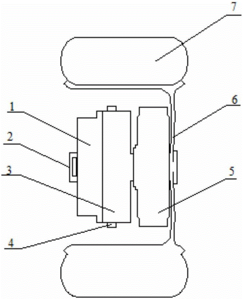
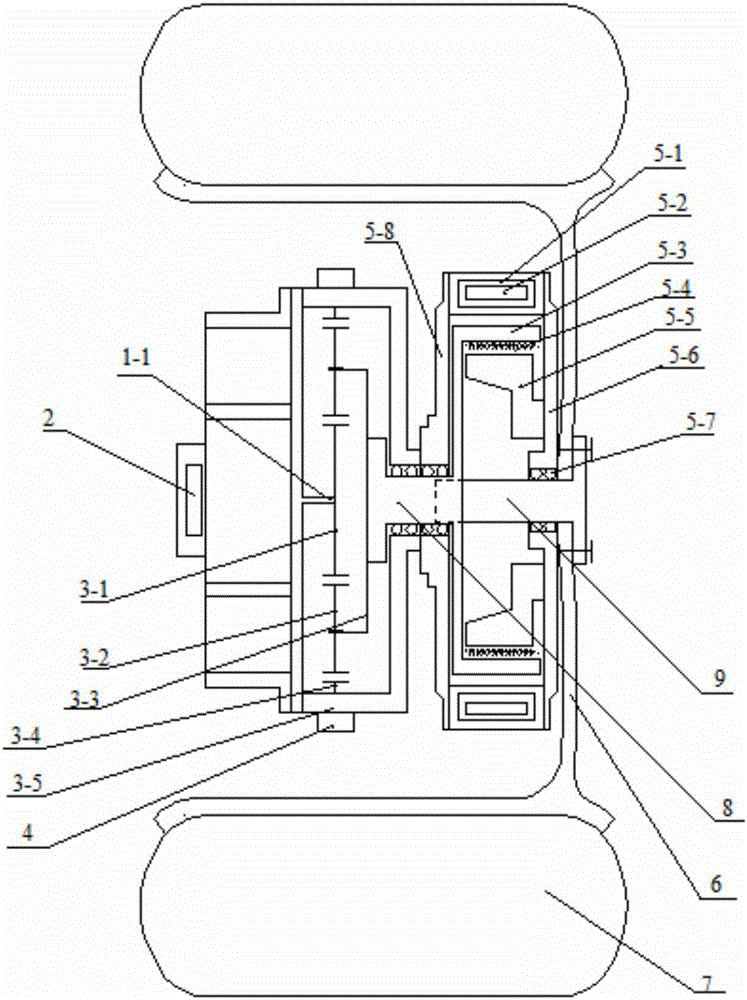
[0042] Such as figure 1 and 2 As shown, the braking system of the hub motor electric vehicle includes the braking device and the control system. The braking device includes an in-wheel motor 1 , a motor controller 2 , a planetary reducer 3 , an electromagnetic actuator 4 , a magnetic powder brake 5 and a vehicle-mounted lithium battery 10 . Each wheel is integrated with a hub motor 1, a motor controller 2, a planetary reducer 3 and a magnetic powder brake 4; the motor controller 2 is fixed on the frame, and the stator (housing) of the hub motor 1 is fixed on the frame. Each hub motor 1 is controlled by a motor controller. The hub motor 1 is connected to the magnetic powder brake 5 through the planetary reducer 3 , and the output shaft 9 of the magnetic powder brake is connected to the hub 6 by bolts; the tire 7 is sleeved on the hub 6 . ...


PUM


Abstract

The invention discloses a wheel hub motor electric car braking system and a braking energy recovery control method. The braking force of a braking system on a traditional electric car is difficult to control, and a storage battery is repeatedly charged and discharged, so that the service life of the storage battery is short. In the wheel hub motor electric car braking system, a wheel hub motor, a motor controller, a planetary reducer and a magnetic powder brake are integrated inside each wheel; each wheel hub motor is controlled by the corresponding motor controller and is connected with the corresponding magnetic powder brake through the corresponding planetary reducer; an output shaft of each magnetic powder brake is connected with a wheel hub through bolts; each gear ring and a corresponding reducer shell form a revolute pair, and each gear ring is connected with the corresponding reducer shell through a plurality of electromagnetic actuators; and the electromagnetic actuators control on-off of power transmission between each wheel hub motor and the corresponding wheel by controlling the corresponding gear ring. The braking energy recovery control method comprises the braking force distribution process and the energy recovering and utilization process. According to the wheel hub motor electric car braking system and the braking energy recovery control method, the feedback braking force and the non-feedback braking force are effectively distributed; the feedback braking force is preferentially used for vehicle-mounted electrical appliances; and when a car is emergently braked, the gear rings idle, so that the motors are protected.

Description

technical field [0001] The invention belongs to the field of electric vehicles, and in particular relates to a braking system of an electric vehicle driven by a hub motor and a braking energy recovery control method. Background technique [0002] With its advantages of zero emission, environmental protection and energy saving, electric vehicles have become a sunrise industry in the automotive field in recent years. The application of in-wheel motors makes the maneuverability of electric vehicles surpass that of traditional vehicles, and greatly simplifies the transmission system of vehicles. One of the bottlenecks currently restricting the development of electric vehicles is that there is still a gap between the cruising range of electric vehicles and traditional vehicles. Therefore, how to improve the cruising range of electric vehicles is one of the hot spots in the field of electric vehicle research. The application of regenerative braking technology on electric vehicle...

Claims


Application Information

Patent Timeline
Patent Type & Authority Applications(China)
IPC IPC(8): B60L7/18B60K7/00B60K17/08B60K17/14
CPCB60K7/0007B60K17/08B60K17/145B60K2007/0061B60K2007/0092B60L7/18
Inventor 孟庆华赵婷婷蔡怀玉陈堂禄
Owner 福建艾密克新能源科技有限公司
Why Eureka
Try Eureka