A multifunctional stepless pressure changing device and abs combined relay valve

A technology of a voltage transformer and a relay valve is applied in the field of ABS combined relay valve and multi-functional stepless voltage transformer, which can solve the problems of prolonged braking time, hidden danger of traffic safety, slow braking response speed, etc. Brake control function, the effect of improving braking sensitivity and shortening braking distance

Inactive Publication Date: 2018-08-31
山东康健汽车科技股份有限公司
View PDF9 Cites 0 Cited by
  • Summary
  • Abstract
  • Description
  • Claims
  • Application Information

AI Technical Summary

Problems solved by technology

The disadvantage is that the relay valve cannot maintain the controllability of the vehicle when the solenoid valve fails or fails
[0008] The structure of the traditional ABS electromagnetic control valve body is simple, and there are many unreasonable conditions. One of the specific manifestations is that the flow rate of the air flow channel distributed to the brake chamber is too small, resulting in slower braking response speed and longer braking time. The second is that in order to achieve the purpose of anti-locking in the overall structure, the ECU controls the leakage of a large amount of brake air pressure, so that the air pressure in the non-locking time period after the "locking" is insufficient, resulting in the overall Poor vehicle deceleration brings major hidden dangers to traffic safety

Method used


Image

  • A multifunctional stepless pressure changing device and abs combined relay valve
  • A multifunctional stepless pressure changing device and abs combined relay valve
  • A multifunctional stepless pressure changing device and abs combined relay valve

Examples


Embodiment 1

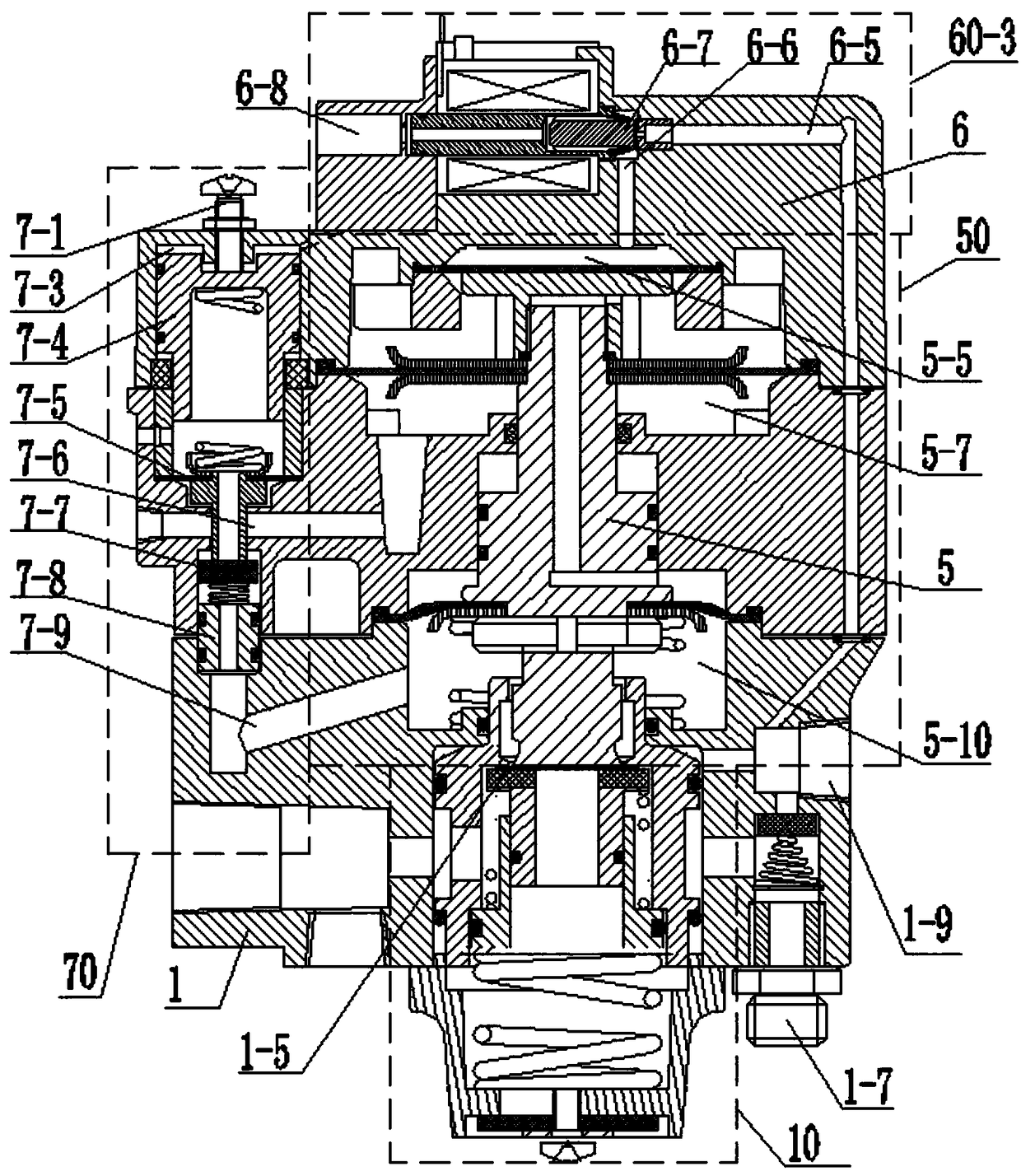
[0068] See figure 2 : figure 2 It is a cross-sectional view of an ABS combined relay valve including a multifunctional stepless pressure changing device, showing the multifunctional stepless pressure changing device, the switch assembly 10, the voltage stabilizing and regulating device 70, and the position and installation relationship of each part.

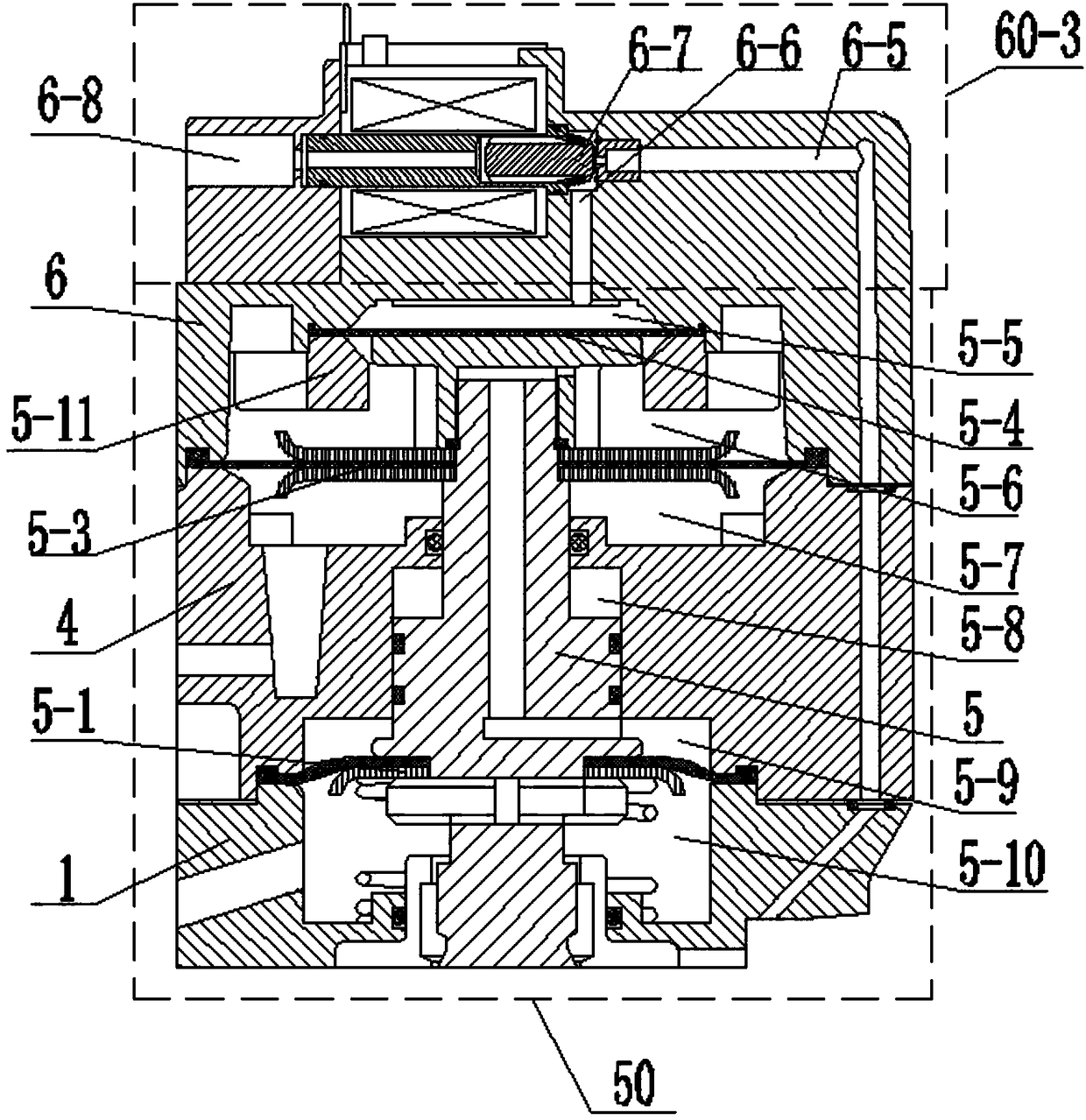
[0069] Depend on figure 1 It can be seen that the lower end surface of the main valve stem 5 of the multi-functional stepless pressure changing device is in contact with the valve 1-5 of the switch assembly 10, the passage 6-5 in front of the valve is connected with the normally open air inlet 1-9, and the normally open air inlet The air holes 1-9 are externally connected to the air storage tank of the main vehicle; the voltage stabilizing and regulating device 70 is connected in series between the two negative pressure chambers of the multifunctional stepless voltage changing device.

[0070] The specific structure of the sw...

Embodiment 2

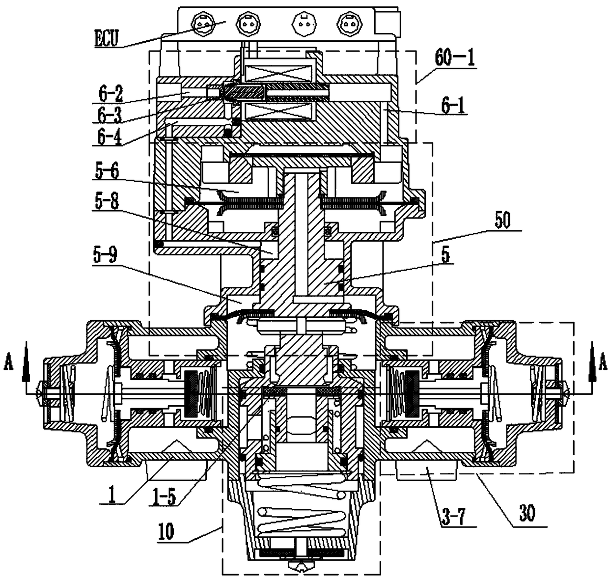
[0076] See image 3 , on the above-mentioned ABS combination relay valve, a first-level anti-locking response device 60 - 1 can also be added, and this device is arranged on the upper cover 6 .

[0077] The first-stage anti-lock braking response device 60-1 of this embodiment includes a pre-valve channel 6-1 communicated with the first working chamber 5-6, and a post-valve channel 6 communicated with the third working chamber 5-8. -4, the pressure relief hole 6-2 directly leading to the atmosphere; a normally closed solenoid valve 6-3 is connected in series between the pressure relief hole 6-2 and the valve front passage 6-1 and the valve rear passage 6-4, and the solenoid valve 6- 3. Controlled by the ECU in the ABS, it controls the communication or isolation of the channel 6-1 before the valve, the channel 6-4 after the valve and the pressure relief hole 6-2. In the ECU control unit of ABS, a first-level anti-lock braking system is added. The system controls the solenoid v...

Embodiment 3

[0083] See Figure 4 , on the above-mentioned ABS combination relay valve, an input air pressure configuration pressure adjustment response device 60 - 2 can also be added, and this device is arranged on the upper cover 6 in this embodiment.

[0084]Input air pressure configuration pressure adjustment response device 60-2 includes control air inlet hole 6-10, control air pressure channel 6-9, configuration valve 6-11, valve stem 6-12, configuration valve diaphragm 6-14, valve front channel 6-13, solenoid valve 6-16, upper valve rear passage 6-15, lower valve rear passage 7-2; among them, control air pressure passage 6-9 and valve front passage 6-13 and first working chamber 5-6 The channel 7-2 after the lower valve communicates with the upper chamber 7-3 of the pressure stabilizing valve of the pressure stabilizing and regulating device 70; the solenoid valve 6-16 is controlled by the ECU in the ABS. In the ECU control unit of ABS, a secondary anti-lock braking system is adde...


PUM


Abstract

The invention relates to a multifunctional stepless transformer. The multifunctional stepless transformer comprises a stepless transformer body which comprises a main valve rod, an upper diaphragm assembly and a lower diaphragm assembly, wherein the upper diaphragm assembly and the lower diaphragm assembly are installed on the main valve rod in a sleeving mode. A high-pressure diaphragm makes contact with the upper end surface of the main valve rod. An inner cavity of a shell body is divided into a high-pressure chamber, a first working chamber, a second working chamber, a third working chamber, a fourth working chamber and a fifth working chamber which do not communicate with one another from top to bottom. A communicating channel is formed between the first working chamber and the fourth working chamber. The multifunctional stepless transformer further comprises a braking immediate cut-in response device communicating with the high-pressure chamber. The invention further relates to an ABS combination relay valve applying the multifunctional stepless transformer. According to the ABS combination relay valve, the high air pressure from a high-pressure air cylinder can directly control a valve body, the braking time is shortened, and the vehicle braking sensitivity is improved.

Description

technical field [0001] The invention relates to the technical field of automobile brakes, and the specific technology is a multifunctional stepless voltage changing device, which belongs to the auxiliary device of an electronic relay valve. [0002] The present invention also relates to an ABS combined relay valve using the multifunctional stepless pressure changing device. Background technique [0003] With the rapid development of the national economy and modern industry, road operations are becoming increasingly busy. At present, the semi-trailer tractors in operation in my country account for more than 70% of the total long-distance transportation. In order to ensure the safe and efficient transportation of vehicles and reduce the accident rate, higher requirements are put forward for the braking system of transportation vehicles. In particular, the braking system of large-tonnage trucks, long-wheelbase semi-trailers, and trailers must have high sensitivity and reliabl...

Claims


Application Information

Patent Timeline
IPC IPC(8): B60T11/224B60T8/1764B60T15/18
CPCB60T8/1764B60T11/224B60T15/18
Inventor 康大为康亚君李欣柏兰英张丰森周忠库李明强李文峰
Owner 山东康健汽车科技股份有限公司
Why Eureka
Try Eureka