A method of measuring and visualizing mine shaft material level based on a small unmanned aerial vehicle

A technology of small unmanned aerial vehicle and chute material level, which is applied in the direction of measuring device, engine lubrication, liquid/fluid solid measurement, etc. It can solve the problems of potential safety hazards, poor inspection effect, complicated detection process, etc., and achieve a wide range of applications , wide application range, fast scanning effect

Active Publication Date: 2018-02-13
TIANJIN UNIV
View PDF11 Cites 0 Cited by
  • Summary
  • Abstract
  • Description
  • Claims
  • Application Information

AI Technical Summary

Problems solved by technology

[0005] 1) The contact measurement mainly adopts the heavy hammer measurement method, the equipment is easy to be damaged, and it is often difficult to control the ultra-deep shaft measurement
The measurement range of ultrasonic, radar, laser and other level meter measurement methods is generally difficult to meet the needs of ultra-deep chute material level measurement, and ultrasonic and radar are not suitable for the measurement of deep narrow chute due to the existence of beam angle, due to the large dust in the chute The farthest measurement range of the laser level gauge alone does not exceed 200 meters
The calculation method of material level based on weighing method has measurement accumulation error, if it cannot be corrected in time, it will easily lead to serious misjudgment
[0006] 2) Manual downhole operations are often used for the inspection of the inner shaft wall of the chute. The workload is huge and the inspection effect is poor. The process is very complicated, and there are also security risks
[0007] 3) The current chute detection method cannot realize the material level measurement and the visualization of the well wall at the same time
The existing method uses relatively complicated equipment, and even needs to renovate the original chute, but only realizes the detection of material level measurement, and the visual detection of the chute wall requires special scanning instruments and supporting facilities
This is a waste of cost and resources, and is not conducive to the implementation of mine automation

Method used


Image

  • A method of measuring and visualizing mine shaft material level based on a small unmanned aerial vehicle
  • A method of measuring and visualizing mine shaft material level based on a small unmanned aerial vehicle

Examples


Embodiment Construction

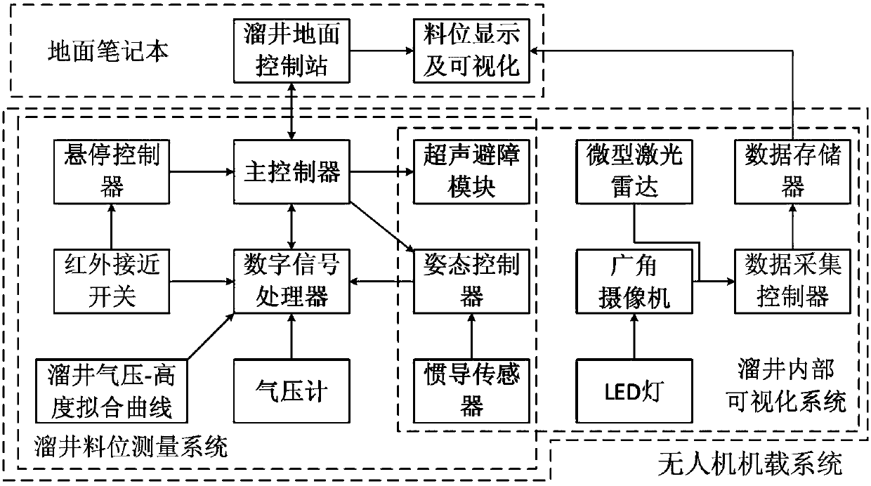
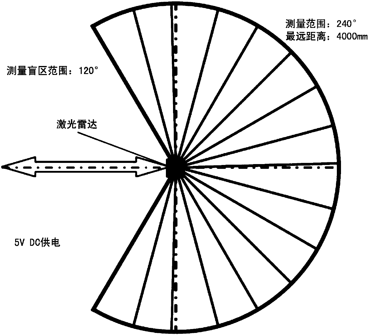
[0022] The stated purpose of the present invention is realized by the small-sized four-rotor unmanned aerial vehicle platform carrying two-dimensional laser radar proposed below. In addition to flight parts, flight control system and battery, the UAV platform also includes ultrasonic obstacle avoidance system, barometer with temperature compensation function, infrared proximity switch, miniature laser radar, miniature wide-angle camera, 256GB high-speed flash memory card, digital signal processor. The technical scheme adopted in the present invention is that the UAV approaches the material level downward along the chute, and the infrared proximity switch directly below it can hover at a certain distance after sensing the material level. The signal processor obtains the depth information of the chute; a small lidar and a miniature wide-angle camera installed on the UAV can provide a complete scan and visualization of the chute wall.

[0023] Technical scheme of the present inv...


PUM


Abstract

The invention relates to a mine chute material level measurement method based on a small unmanned aerial vehicle and a visualization method. The method comprises following steps: air pressure of multiple points whose height is known is measured by a barometer with a temperature compensating function, and an approximate linear relationship curve of the air pressure inside the chute and height is fitted according to the measured data; the unmanned aerial vehicle flies downwards from the top ground plane of the chute and the unmanned aerial vehicle approaches the up side of the material level and is kept hovering; the material level value is calculated according to the signals of the barometer; the complete well wall micro laser ray scanning data and surface image information are obtained; the scanning data and the surface information are reconstructed and visualized for check. The method has the advantages such as easy measurement of material level, flexible and wide application range.

Description

technical field [0001] The invention belongs to the field of mine automation instrument measurement, in particular to a mine chute material level measurement and visualization method based on a small unmanned aerial vehicle platform. Background technique [0002] The chute is an important channel for underground mines to slid and temporarily store ore, which plays a very important role in improving production efficiency and saving costs. In mine production, in order to ensure safe production and coordinate the dispatching of mining and ore transport locomotives, it is necessary to grasp the real-time material level of each chute in time, so the measurement of mine chute material level is of great importance. From the perspective of mine safety production, in order to prevent the impact of the upper scraper unloading on the ore-drawing device of the chute, it is necessary to maintain a certain material level as a buffer, otherwise the equipment will be damaged and production ...

Claims


Application Information

Patent Timeline
Patent Type & Authority Patents(China)
IPC IPC(8): G01F23/292
CPCG01F23/292
Inventor 孟庆浩亓培锋曾明
Owner TIANJIN UNIV
Why Eureka
Try Eureka