
Array substrate, touch display device and driving method thereof

A technology for a touch display device and an array substrate, which is applied in the fields of instruments, electrical digital data processing, and data processing input/output processes, etc., can solve the problem that the display device is difficult to achieve a narrow frame, the touch drive circuit is complex, and the output signals are many. and other problems, to achieve the effect of improving the touch point reporting rate, narrowing the frame, and reducing the output signal

Active Publication Date: 2018-09-07
XIAMEN TIANMA MICRO ELECTRONICS +1
View PDF4 Cites 0 Cited by
  • Summary
  • Abstract
  • Description
  • Claims
  • Application Information

AI Technical Summary

Problems solved by technology

[0002] In the prior art, in order to realize the touch function, touch driving electrodes need to be provided in the display device. However, the touch driving circuit for providing touch driving signals to the touch driving electrodes is relatively complicated, which makes it difficult for the corresponding display device to realize narrow frame
In addition, since the touch driving circuit has more signal input terminals, the touch driving circuit needs more output signals from an integrated control circuit (Integrated Circuit, IC for short), thereby increasing the cost of the IC.

Method used


Image

  • Array substrate, touch display device and driving method thereof
  • Array substrate, touch display device and driving method thereof
  • Array substrate, touch display device and driving method thereof

Examples


Embodiment Construction

[0071] Example embodiments will now be described more fully with reference to the accompanying drawings. Example embodiments may, however, be embodied in many forms and should not be construed as limited to the examples set forth herein; rather, these embodiments are provided so that this disclosure will be thorough and complete and will fully convey the concept of example embodiments to those skilled in the art. The drawings are merely schematic illustrations of the invention and are not necessarily drawn to scale. The same reference numerals in the drawings denote the same or similar parts, and thus repeated descriptions thereof will be omitted.

[0072] Furthermore, the described features, structures, or characteristics may be combined in any suitable manner in one or more embodiments. In the following description, numerous specific details are provided in order to give a thorough understanding of embodiments of the invention. However, those skilled in the art will appre...


PUM


Abstract

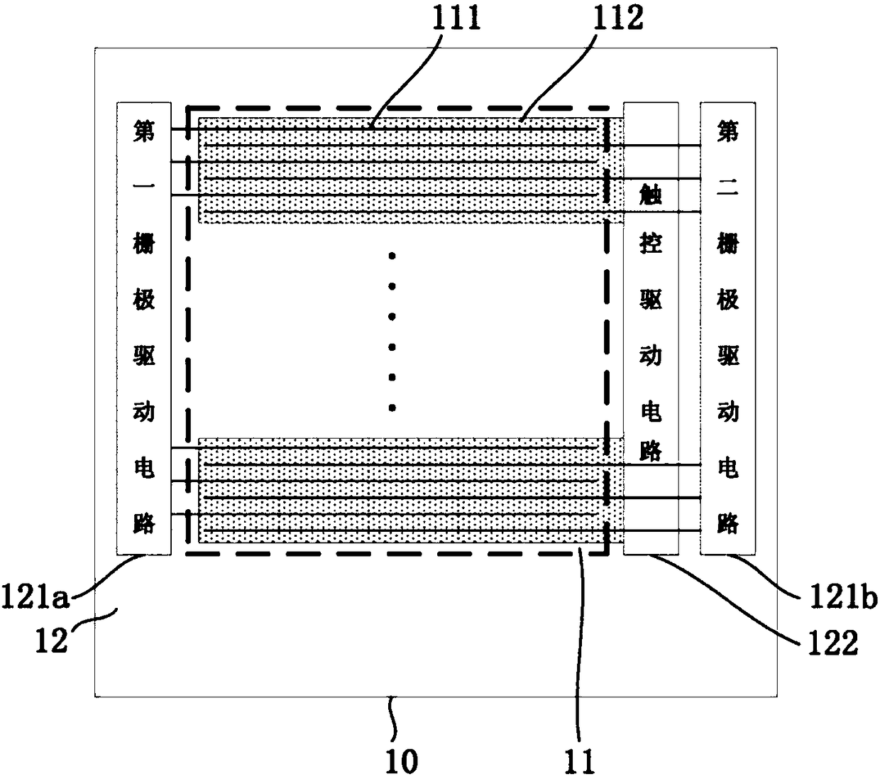
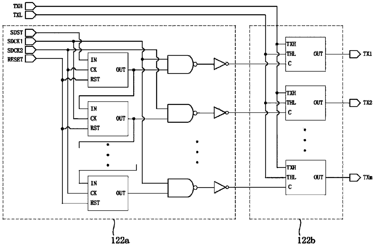
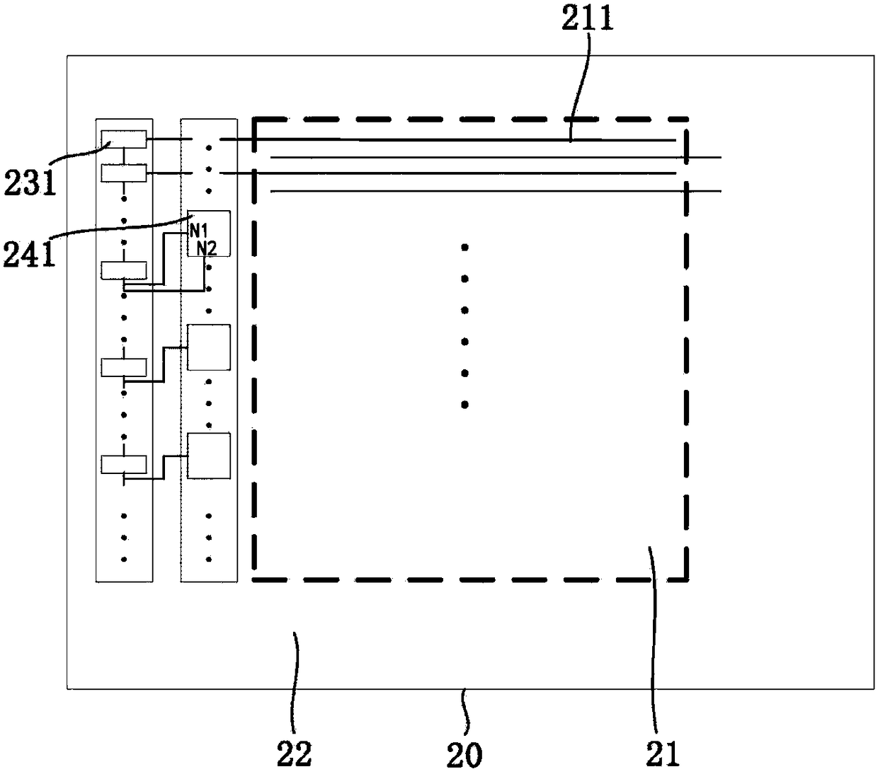
The invention relates to an array substrate, a touch display device, and a driving method thereof. The array substrate includes a display region and a peripheral region surrounding the display region. The display region includes N rows of scanning lines, wherein N is a positive integer more than 1. The peripheral region includes a touch driving circuit and a gate driving circuit, wherein, the touch driving circuit includes M stages of touch output units for generating touch driving signals, where M is an integer more than 0 and less than or equal to N; the gate driving circuit includes N stages of shift registers for said N rows of scanning lines which generate scanning signals. The M stages of shift registers include a first strobe signal output terminal and a second strobe signal output terminal, which provide a first strobe signal and a second strobe signal for the M stages of touch output units, respectively; the touch output unit includes PMOS tubes from the first one to the eleventh one. The invention uses the signal in the shift register as the input strobe signal of the touch driving circuit to realize narrow border.

Description

technical field [0001] The present invention generally relates to the field of display technology, and in particular, relates to an array substrate, a touch display device and a driving method thereof. Background technique [0002] In the prior art, in order to realize the touch function, touch driving electrodes need to be provided in the display device. However, the touch driving circuit for providing touch driving signals to the touch driving electrodes is relatively complicated, which makes it difficult for the corresponding display device to realize narrow frame. In addition, since the touch driving circuit has more signal input terminals, the touch driving circuit needs more output signals from an integrated control circuit (Integrated Circuit, IC for short), thereby increasing the cost of the IC. [0003] Therefore, a new array substrate and a touch display device are needed to solve the above problems. [0004] The above information disclosed in this Background sec...

Claims


Application Information

Patent Timeline
Patent Type & Authority Patents(China)
IPC IPC(8): G06F3/041
CPCG06F3/0412
Inventor 孙莹许育民
Owner XIAMEN TIANMA MICRO ELECTRONICS
Learn More