Demodulation circuit used in a passive ultrahigh frequency radio-frequency identification label chip

A technology of radio frequency identification tags and demodulation circuits, applied in the field of analog integrated circuits, can solve the problems of increasing chip area and power consumption, complex structure, large area, etc., and achieve the effects of reducing chip area, improving sensitivity, and increasing working distance

Active Publication Date: 2016-09-21
XIANGTAN UNIV
View PDF4 Cites 11 Cited by
  • Summary
  • Abstract
  • Description
  • Claims
  • Application Information

AI Technical Summary

Problems solved by technology

Demodulation circuits are usually divided into voltage-type and current-type; current-type demodulation circuits usually convert voltage signals into current signals for processing, and their structures are often complex
The voltage-type demodulation circuit has a simple structure and is easy to implement, but the traditional voltage-type demodulation circuit uses Schottky diodes as the envelope detection circuit, which will bring relatively high costs in the standard CMOS process
The method of using internal and external threshold compensation will increase additional chip area and power consumption
In addition, the reference level generation circuit in the demodulator adopts the method of resistive voltage division, which will bring a relatively large area

Method used


Image

  • Demodulation circuit used in a passive ultrahigh frequency radio-frequency identification label chip
  • Demodulation circuit used in a passive ultrahigh frequency radio-frequency identification label chip
  • Demodulation circuit used in a passive ultrahigh frequency radio-frequency identification label chip

Examples


Embodiment Construction

[0018] The present invention will be further described below in conjunction with the accompanying drawings and embodiments.

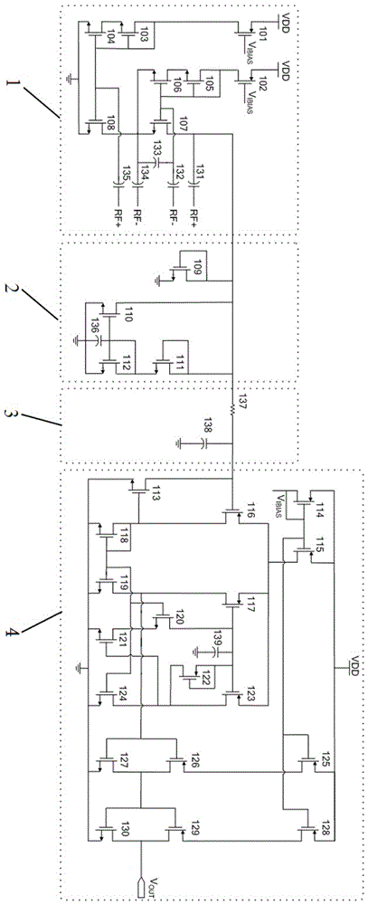
[0019] like figure 1As shown, the present invention includes an envelope detection circuit 1, a voltage limiting circuit 2, a low-pass filter circuit 3, a reference level generation and comparison output circuit 4 connected in series, and the envelope detection circuit 1 includes a first PMOS transistor 101 , the second PMOS transistor 102, the first NMOS transistor 103, the second NMOS transistor 104, the third NMOS transistor 105, the fourth NMOS transistor 106, the fifth NMOS transistor 107, the sixth NMOS transistor 108, the first capacitor 131, the second Capacitor 132, third capacitor 133, fourth capacitor 134, fifth capacitor 135, the sources of the first PMOS transistor 101 and the second PMOS transistor 102 are connected to high level, the grid of the first PMOS transistor 101 is connected to the second PMOS transistor 102 is connected to the ...


PUM


Abstract

The invention discloses a demodulation circuit used in a passive ultrahigh frequency radio-frequency identification label chip, and the circuit comprises an envelope detection circuit, a voltage limiting circuit, a low-pass filter circuit, a reference level generation and comparison output circuit. All are in series connection in the order as they are listed aforementioned. The envelope detection circuit of the invention adopts the method of active envelope detection to restore a baseband signal modulated on a high-frequency carrier wave, and the restored envelope signal is limited to the common-mode input range of the latter-stage circuit through the voltage limiting circuit, and then through the low-pass filter circuit, noise signals in the filter high-frequency carrier wave and the environment are filtered before being transmitted to the reference level generation and comparison output circuit where they are compared to the reference level. Following that, digital signals are outputted for digital baseband processing. With high sensitivity yet low power consumption, the circuit is also small in size.

Description

technical field [0001] The invention relates to the field of analog integrated circuits, in particular to a demodulation circuit applied to passive ultra-high frequency radio frequency identification tag chips. Background technique [0002] As an automatic identification technology, radio frequency identification (RFID) has the advantages of fast reading speed, long life, reusable, small size, large data storage capacity and less affected by the external environment compared with traditional barcodes, especially Passive UHF RFID has the characteristics of long identification distance. This technology is widely used in logistics warehouse management, manufacturing, retail, postal express and other service and production fields. [0003] Usually the basic RFID system is mainly composed of RFID tags, readers, antennas, middleware and application software. As the real carrier of data, RFID tags are composed of tag chips and antennas. The tag chip is mainly composed of RF analo...

Claims


Application Information

Patent Timeline
Patent Type & Authority Applications(China)
IPC IPC(8): G06K19/07
CPCG06K19/0723
Inventor 唐明华梁赛儿杨黎
Owner XIANGTAN UNIV
Why Eureka
Try Eureka