A shale pore imaging method and device

An imaging method and shale technology, applied in image generation, image data processing, 2D image generation, etc., can solve problems such as local value interference, unstable results, and difficulty in accurately realizing shale micro-nano-pore fracture research, etc. , to achieve the effect of improving imaging resolution and reducing phase information

Active Publication Date: 2017-10-27
INST OF GEOLOGY & GEOPHYSICS CHINESE ACAD OF SCI
View PDF3 Cites 1 Cited by
  • Summary
  • Abstract
  • Description
  • Claims
  • Application Information

AI Technical Summary

Problems solved by technology

[0003] After patent retrieval and domestic and foreign literature research, it is found that the current methods of using phase information to process shale pore X-ray projection data mostly use the frequency domain filtering method. This method eliminates the phase effect through the filtering function, and has limited imaging resolution, and It is easy to be disturbed by local values, leading to unstable results and other problems, and it is difficult to accurately realize the research of micro-nano pores and fractures in shale
[0004] In view of the above-mentioned method of shale pore imaging using the frequency domain filtering method, the imaging resolution is limited, and the results are easily disturbed by local values, resulting in unstable results. No effective solution has been proposed yet.

Method used


Image

  • A shale pore imaging method and device
  • A shale pore imaging method and device
  • A shale pore imaging method and device

Examples


Embodiment 1

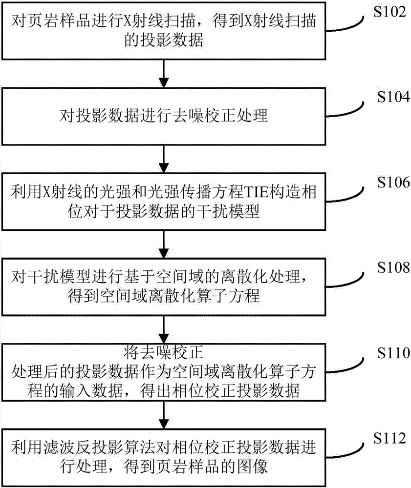
[0044] see figure 1 The flow chart of the shale pore imaging method shown, the method includes the following steps:

[0045] Step S102, X-ray scanning is performed on the shale sample to obtain projection data of the X-ray scanning.

[0046] The above process of X-ray scanning of shale samples is carried out under laboratory conditions. The X-ray light source may be a parallel light source, and the shale samples are scanned to obtain projection data, wherein the projection data includes phase information of the shale samples.

[0047] Step S104, performing denoising and correction processing on the projection data.

[0048] The projection data of the above shale samples is the projection data containing phase information obtained by X-ray scanning of shale samples under laboratory conditions. Considering that noise and errors will be generated under laboratory conditions, including those caused by X-ray light sources Bright and dark field noise, device position offset, and s...

Embodiment 2

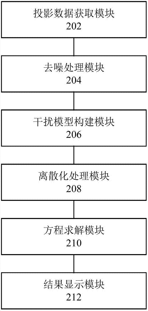
[0074] Corresponding to the methods provided in the above embodiments, the embodiments of the present invention also provide a device for imaging shale voids, see figure 2 , the device consists of the following modules:

[0075]The projection data acquisition module 202 is configured to perform X-ray scanning on the shale sample to obtain X-ray scanning projection data, wherein the projection data includes phase information of the shale sample.

[0076] The denoising processing module 204 is used to perform denoising and correction processing on the projection data, which can remove bright and dark field noise and correct the position offset of the device in the experiment.

[0077] The interference model building module 206 is configured to use the X-ray light intensity and the light intensity propagation equation TIE to construct a phase-to-projection data interference model, wherein the interference model is an interference model obtained by considering the influence of no...


PUM


Abstract

The invention provides a shale pore imaging method and a device, wherein the method comprises the steps: X-ray scanning is performed on a shale sample to obtain projection data of X-ray scanning; noise elimination correction processing is performed on the projection data; light intensity of X-ray and transport of intensity equation TIE are adopted to construct a phase interference model of the above projection data; discretization process is performed on the interference model based on a spatial domain, and a spatial domain discretization operator equation is obtained; the processed projection data serves as input data of the spatial domain discretization operator equation, and phase correction projection data is obtained; a filter back projection algorithm is utilized to process the above phase correction projection data, and an image of the shale sample is obtained. According to the invention, a method for solving the spatial domain is adopted, the interference of the phase information is reduced, resistance effect for noise is also presented, and meticulous expression can be performed on nanoscale pore throat and millimeter-scale and micron-scale pores of the shale sample.

Description

technical field [0001] The invention relates to the technical field of geophysical detection, in particular to a shale pore imaging method and device. Background technique [0002] In recent years, shale has attracted extensive attention due to its abundant oil and gas resources. The pore structure of shale oil and gas reservoirs is complex and diverse, mainly nano-scale pore-throat systems. Therefore, if micro-nano-scale imaging of shale can be realized, it will It is of great significance to study geological problems such as oil and gas occurrence state and migration mode. It is difficult to study the micro-nano pores and fractures of shale non-destructively by traditional methods. Even X-ray scanning still has difficulties such as insufficient resolution, low signal-to-noise ratio, and difficulty in imaging weakly absorbing objects. When the distance is large, there will be serious phase interference problems. The introduction of the third-generation synchrotron radiati...

Claims


Application Information

Patent Timeline
Patent Type & Authority Patents(China)
IPC IPC(8): G06T11/00
CPCG06T11/008G06T2211/40
Inventor 王彦飞唐巍
Owner INST OF GEOLOGY & GEOPHYSICS CHINESE ACAD OF SCI
Why Eureka
Try Eureka