Control method of three-phase dual-active-bridge DC converter under current optimal modulation

A DC converter and dual active bridge technology, which is applied in the direction of converting DC power input to DC power output, adjusting electrical variables, and controlling/regulating systems, etc. , Switch device stress imbalance and other issues

Inactive Publication Date: 2016-09-21
XI AN JIAOTONG UNIV
View PDF5 Cites 12 Cited by
  • Summary
  • Abstract
  • Description
  • Claims
  • Application Information

AI Technical Summary

Problems solved by technology

This will cause the problem of unbalanced stress of switching devices, and at the same time, due to the l

Method used


Image

  • Control method of three-phase dual-active-bridge DC converter under current optimal modulation
  • Control method of three-phase dual-active-bridge DC converter under current optimal modulation
  • Control method of three-phase dual-active-bridge DC converter under current optimal modulation

Examples


Embodiment Construction

[0031] The present invention will be further described in detail below in conjunction with specific embodiments, which are explanations of the present invention rather than limitations.

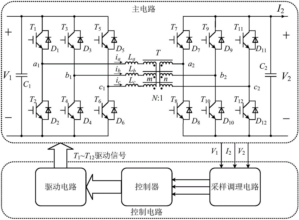
[0032] The topology of the three-phase isolated bidirectional DC converter is as follows: figure 1 shown. where, assuming the power is from V 1 Side flow to V 2 side, the V 1 is the input side DC voltage, V 2 is the output DC voltage. Taking phase a as an example, V a1 is the three-phase transformer V 1 side a phase voltage, V a2 is the three-phase transformer V 2 Phase a voltage of side a, V′ a2 is converted to V through the transformer 1 side V 2 side a-phase voltage, that is, V′ a2 =NV a2 , i a is the transformer phase a current, L aIt is the leakage inductance of phase a of the transformer, and so on for other phases. N:1 is the transformation ratio of the transformer.

[0033] A set of basic parameters for setting the converter is shown in Table 1.

[0034] Table 1

[...


PUM


Abstract

The invention provides a control method of a three-phase dual-active-bridge DC converter under a current optimal modulation. The method comprises a step of collecting DC side output voltage V2, DC side output current I2 and DC side input voltage V1 in each switch cycle, a step of multiplying the collected V2 by I2 to obtain a transmission power Po, at the same time multiplying V2 by a transformer transformation ratio N, dividing the above product by V1, and obtain a voltage transformation ratio d, a step of allowing Po and d to go through an optimal modulation strategy link to obtain the reference value D1* and D2* of duty ratios D1 and D2, and then obtaining the duty ratios D1 and D2 through two large inertia links or pure integrator links, a step of allowing the duty ratios D1 and D2 to go through an optimal amplitude limit value calculation link, and obtaining the optimal amplitude limit value Df_lim of a phase shift ratio, a step of carrying out difference comparison on a DC side output reference value V2ref and V2, allowing a difference to go through a PI regulator and an amplitude limit link with an amplitude limit value, and obtaining a phase shift ratio Df, and a step of obtaining the driving signal of each switch device according to the duty ratios D1 and D2 and the phase shift ratio Df, and driving a corresponding switch device.

Description

Technical field: [0001] The invention belongs to the technical field of three-phase dual-active bridge-type DC converters, and in particular relates to a control method for a three-phase dual-active bridge-type DC converter under optimal current modulation. Background technique: [0002] The existing three-phase dual active bridge DC converter consists of a three-phase high-frequency transformer connected to two three-phase bridge circuits. Its topology is as follows: figure 1 shown. It is an isolated bidirectional DC converter. It has the advantages of high power density, low switching stress and easy realization of soft switching. In addition, compared with the single-phase converter, this converter adopts a three-phase interleaved structure, which improves the power level and reduces the current ripple. It is suitable for medium and high power applications, suitable for hybrid electric vehicles, power electronic transformers, and smart grid energy storage systems. [...

Claims


Application Information

Patent Timeline
IPC IPC(8): H02M3/335H02M1/088
CPCH02M1/088H02M3/3353H02M1/0054H02M1/0048Y02B70/10
Inventor 王跃李卓强施伶崔耀黄珺雷万钧
Owner XI AN JIAOTONG UNIV
Why Eureka
Try Eureka