Cutting jig for PU panel

A jig and cutting technology, which is applied in the field of mechanical processing, can solve problems such as plate cracking, saw blade deformation, and affecting efficiency, and achieve the effects of cleaning the processing environment, preventing environmental pollution, and improving processing accuracy

Inactive Publication Date: 2016-09-28
SUZHOU ZHUOCHENG TITANIUM EQUIP
View PDF6 Cites 2 Cited by
  • Summary
  • Abstract
  • Description
  • Claims
  • Application Information

AI Technical Summary

Problems solved by technology

In terms of plate processing and production, usually a drill press or an electric saw is used to cut and punch the plate to meet the production requirements, but there is no equipment specially used for PU plate cutting at present. Cutting soft materials such as wood, or for cutting hard materials such as metal or stone; because the required saw blades are different, the materials are also different, which has led to cutting PU with electric saws in the prior art. Many problems can arise when
For example, cutting the PU board with a hard saw blade will cause the board to crack, causing the fracture to be uneven and difficult to meet the use requirements; using a soft saw blade to cut the PU board will result in inability to cut quickly and affect efficiency; due to the low hardness and insufficient rigidity of the board itself When cutting, it is easy to be carried by the saw blade and deformed, which affects the processing quality, etc.
[0003] To sum up, the existing equipment cannot meet the effective processing of PU sheet, so it is necessary to develop a new type of cutting equipment to meet the processing requirements of the sheet

Method used


Image

  • Cutting jig for PU panel
  • Cutting jig for PU panel
  • Cutting jig for PU panel

Examples


Embodiment Construction

[0024] The present invention will be further described below in conjunction with the accompanying drawings. The following examples are only used to illustrate the technical solution of the present invention more clearly, but not to limit the protection scope of the present invention.

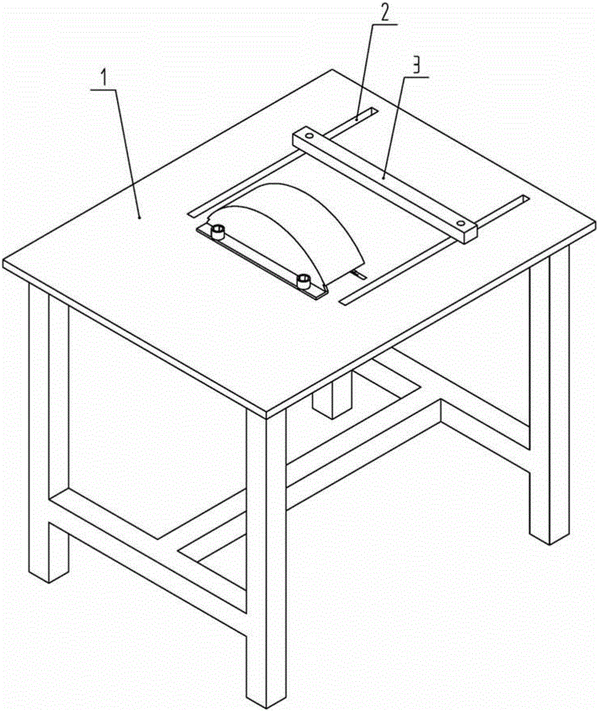
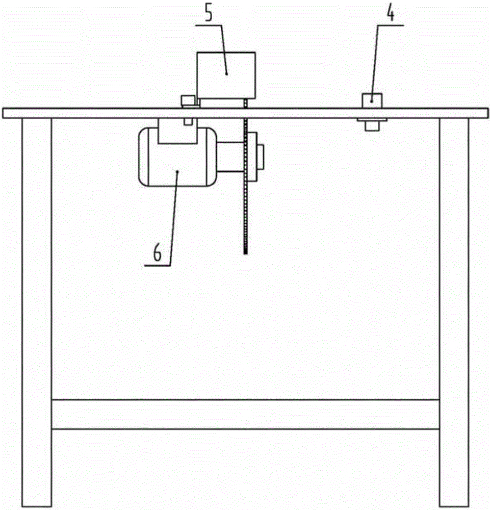
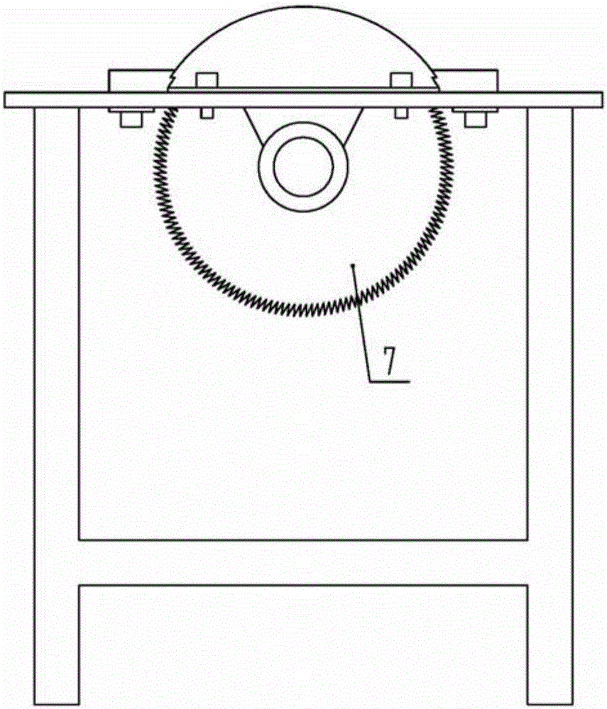
[0025] Such as Figures 1 to 5 As shown, a PU cutting fixture includes a machine platform 1, a driving device 6 installed on the bottom of the machine platform 1, a saw blade 7 installed on the output end of the driving device 6, and a backer capable of sliding on the surface of the machine platform 1. 3, and the dust washing device for dust collection. There is a saw groove on the table of machine 1 that allows the saw blade 7 to protrude. A pair of long grooves 2 perpendicular to the saw blade 7 are provided on the table of machine 1. Guide bolts 4 are installed at both ends of the backing 3, and the backing 3 passes through The guide bolts 4 at both ends are slidingly installed with the lon...


PUM


Abstract

The invention discloses a cutting jig for a PU panel. The cutting jig comprises a machine table, a driving device mounted on the bottom of the machine table, and a saw blade mounted on an output end of the driving device, and further comprises a backer, wherein a saw groove for allowing the saw blade to stretch out is formed in the table surface of the machine table; a pair of long grooves perpendicular to the saw blade is formed in the table surface of the machine table; guide bolts are mounted at the two ends of the backer; the backer and the long grooves are slidably assembled through the guide bolts at the two ends; lock nuts are further mounted on the guide bolts in a matching manner to lock the backer on the machine table; locating scale lines are further printed in the positions, close to notches of the long grooves, on the table surface of the machine table; a pressing cover covering the upper part of the saw blade is mounted on the table surface of the machine table; and a clearance for allowing a workpiece to pass through exists between the bottom of the pressing cover and the table surface of the machine table. According to the cutting jig, the pressing cover is mounted on the table surface of the machine table, so that on one hand, the pressing cover produces the function of a dust shield to prevent chips from splashing to injure a user, and on the other hand, the pressing cover acts as a guide part to firmly press the PU panel on the table surface of the machine table to prevent a tilting phenomenon.

Description

technical field [0001] The invention belongs to the technical field of mechanical processing, and in particular relates to a PU cutting jig. Background technique [0002] PU, which means polyurethane, is the English abbreviation of polyurethane. It is a polymer material and a new organic polymer material. It is known as the "fifth largest plastic" because of its excellent performance. It is widely used in many fields of national economy. The product application fields involve light industry, chemical industry, electronics, textile, medical treatment, construction, building materials, automobile, national defense, aerospace, aviation, etc., and the common PU material in the civilian field is PU board. In terms of plate processing and production, usually a drill press or an electric saw is used to cut and punch the plate to meet the production requirements, but there is no equipment specially used for PU plate cutting at present. Cutting soft materials such as wood, or for c...

Claims


Application Information

Patent Timeline
Patent Type & Authority Applications(China)
IPC IPC(8): B26D1/15B26D7/22B26D7/18B26D7/26B26D7/02B26D7/28
CPCB26D1/15B26D7/025B26D7/1863B26D7/22B26D7/2635B26D7/28
Inventor 陆琦
Owner SUZHOU ZHUOCHENG TITANIUM EQUIP
Why Eureka
Try Eureka