
High-performance crowned tooth coupler

A drum-shaped tooth and coupling technology, which is applied to elastic couplings, couplings, mechanical equipment, etc., can solve the problems of low bearing capacity, low working life, and increase the cost of spare parts, so as to reduce production costs and improve Flexural strength, the effect of prolonging the service life

Active Publication Date: 2016-09-28
TAIER HEAVY IND
View PDF7 Cites 4 Cited by
  • Summary
  • Abstract
  • Description
  • Claims
  • Application Information

AI Technical Summary

Problems solved by technology

[0004] The disadvantages of the existing drum-shaped gear couplings are: 1. The existing drum-shaped gear couplings fail to conduct in-depth research on the motion mechanism of the transmission parts. , The parameters such as the pressure angle, addendum height coefficient, dedendum height coefficient, and displacement circle radius of the internal gear ring at the driving end and the internal gear ring at the driven end are unreasonable, resulting in low load-carrying capacity and low working life of the product; 2. The inner ring gear at the driving end and the inner ring gear at the driven end adopt convex-convex (concave-convex) spigot positioning, and the inner ring gear at the driving end and the inner ring gear at the driven end are not interchangeable, which increases the cost of spare parts; 3. The gland is integrated In this way, it is impossible to replace the seals of wearing parts online. Sometimes, the outer gear sleeve needs to be removed before replacement, which increases the workload of inspection and maintenance, affects the production efficiency of the rolling mill, and increases the labor intensity of maintenance.

Method used


Image

  • High-performance crowned tooth coupler
  • High-performance crowned tooth coupler
  • High-performance crowned tooth coupler

Examples


Embodiment Construction

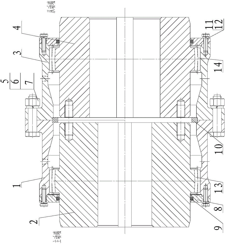
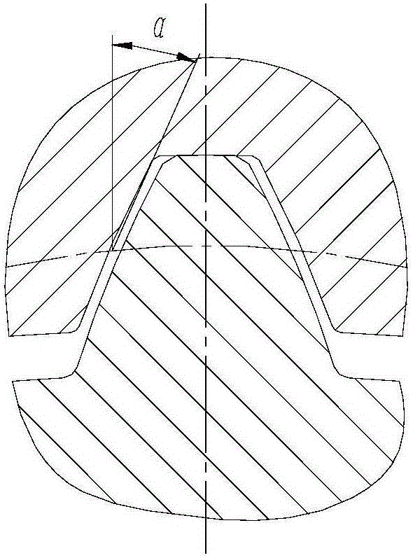
[0017] from figure 1 , figure 2 It can be seen that a high-performance drum-shaped gear coupling of the present invention includes an internal gear ring 1 at the driving end, an external gear sleeve 2 at the driving end, a gear pair 13 connecting the two, an internal gear ring 3 at the driven end, The driven end external gear sleeve 4, the gear pair 14 connecting the two, it also includes the combined gland 8 at both ends, the seal 9, the connection structure of the driving end; the driving end internal gear ring 1 and the driving end external gear shaft The pressure angle α of the sleeve 2 is 20°-30°, and the pressure angle α between the inner ring gear 3 at the driven end and the outer gear sleeve 4 at the driven end is 20°-30°.

[0018] As an improvement of the present invention, the displacement circle radius (R / d) of the external gear sleeve 2 at the driving end and the external gear sleeve 4 at the driven end is 0.8-1.2, the addendum height coefficient is 0.7-1.0, and...


PUM


Abstract

The invention discloses a high-performance crowned tooth coupler which comprises a driving end inner tooth ring, a driving end outer tooth shaft sleeve, a gear pair connecting the driving end inner tooth ring with the driving end outer tooth shaft sleeve, a driven end inner tooth ring, a driven end outer tooth shaft sleeve, and a gear pair connecting the driven end inner tooth ring with the driven end outer tooth shaft sleeve. The high-performance crowned tooth coupler further comprises combination pressing covers at the two ends, seals, and a connecting structure of a driving end and a driven end, wherein pressure angle alpha between the driving end inner tooth ring and the driving end outer tooth shaft sleeve is 20-30 degrees; and pressure angle alpha between the driven end inner tooth ring and the driven end outer tooth shaft sleeve is 20-30 degrees. With the adoption of the scheme, the carrying capacity of the high-performance crowned tooth coupler is improved, the service life is prolonged, and the production cost is reduced. In addition, the driving end inner tooth ring and the driven end inner tooth ring can be exchanged completely, so that the inventory cost of spare parts is reduced. Furthermore, the quick-worn seals of can be replaced online, so that the maintenance downtime is shortened, and the maintenance labor intensity is reduced.

Description

technical field [0001] The invention relates to a drum-shaped gear coupling, which can be widely used in the connection between a motor and a reducer, between a motor and equipment, and between a reducer and equipment. Background technique [0002] The drum gear coupling is an important mechanical basic component. Its function is to connect the driving shaft and the driven shaft, and transmit torque to make the two shafts rotate together. In engineering use, due to manufacturing and installation errors, deformation and wear of parts, subsidence of the foundation, etc., the axis position of the two axes will deviate, and axial displacement, radial displacement, angular displacement and comprehensive displacement will occur. The existence of offset causes additional dynamic loads on shafts, bearings, and couplings, causing vibrations and deteriorating the working conditions of machine parts. Among the various types of couplings, the drum-shaped gear coupling has the advantage...

Claims


Application Information

Patent Timeline
Patent Type & Authority Applications(China)
IPC IPC(8): F16D3/18
CPCF16D3/18
Inventor 张殿龙雷海涛卢茜莉江长娟
Owner TAIER HEAVY IND
Learn More