Reverse-flow type pulse detonation combustor
A technology of pulse detonation and combustion chamber, which is applied in the direction of combustion chamber, continuous combustion chamber, combustion method, etc., can solve the problems of the length of the whole engine, the increase of the axial distance between the turbine and the compressor, etc., and achieve shortening of the axial distance, The effect of improving work stability and prolonging the use time
- Summary
- Abstract
- Description
- Claims
- Application Information
AI Technical Summary
Problems solved by technology
Method used
Image

Examples
Embodiment approach 1
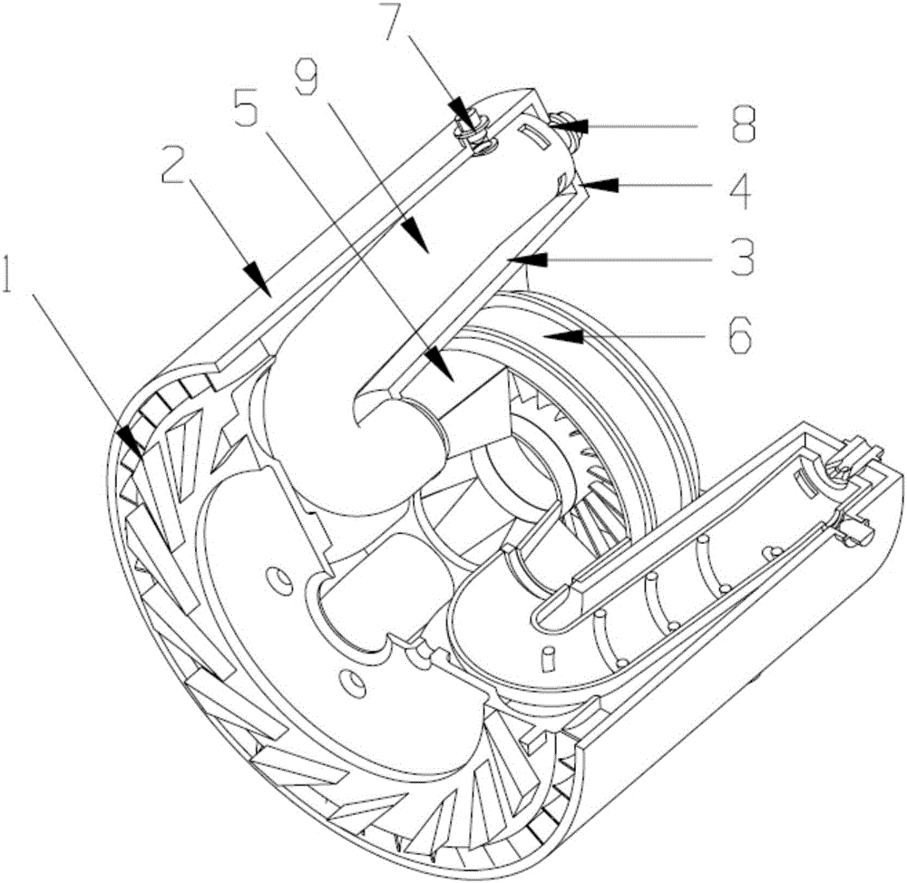
[0025] The diffuser structure 1 of the backflow pulse detonation combustor in this example can be changed according to the form of the compressor. In this embodiment, 15 radial triangular diffuser blades are evenly distributed on the diffuser disc, corresponding to The adjacent triangular diffuser blades are spaced at 24°. There are 40 rectifying blades evenly distributed in the circumferential direction of the diffuser disc, the inlet of the blade is 45° to the axial direction, and the outlet is parallel to the axial direction. The diffuser is linked with the casing through rectifying vanes, and there are 4 bolt holes on the diffuser disc for fixing the bearings.
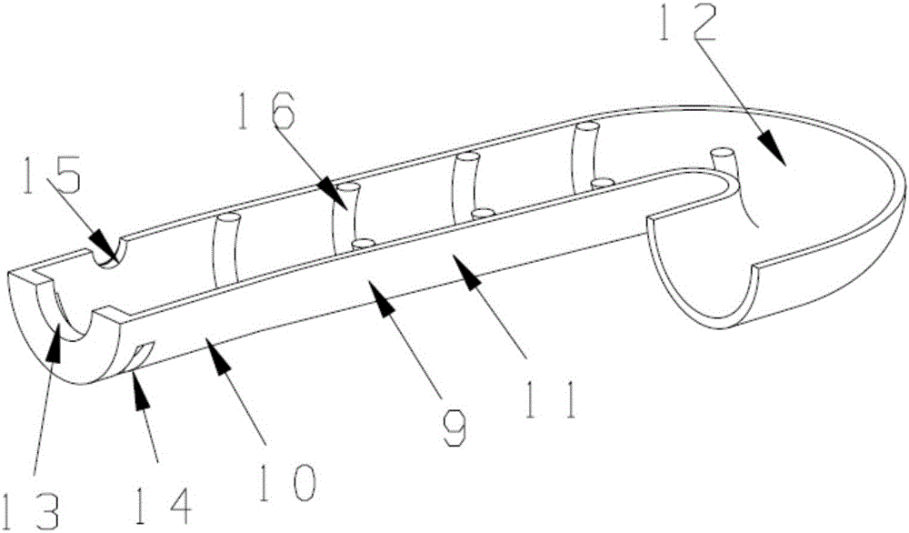
[0026] The recirculation pulse detonation combustor in this example contains 6 J-type recirculation detonation tubes A-type 9, see figure 2 , each detonation tube is composed of a mixing section 10, a detonation straight section 11, and an exhaust curved section 12. The central axis of the detonation tube is even...
Embodiment approach 2
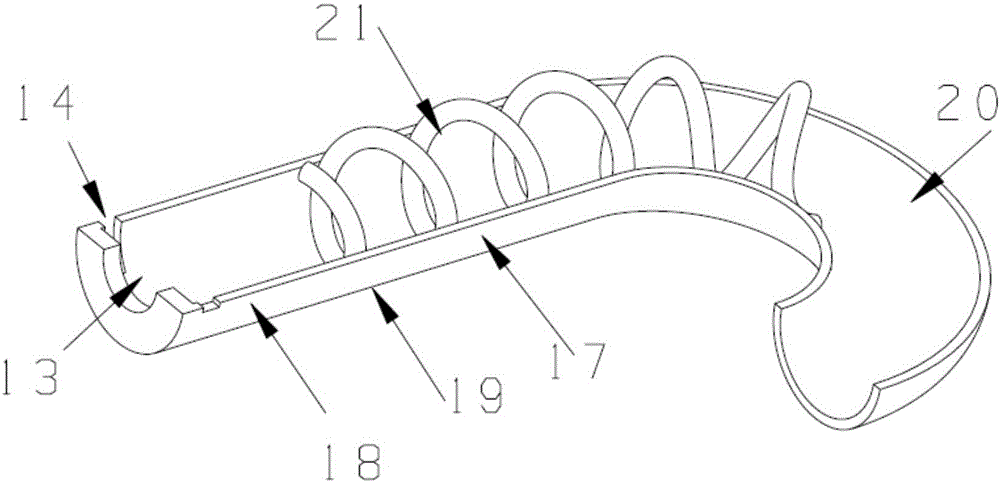
[0029] The recirculation pulse detonation combustor in this example contains 6 J-type recirculation detonation tubes B type 17 see image 3 , Type B is relatively with Type A, there is no angle between its intake mixing section 18 and detonation straight section 19, and its exhaust bend section 20 is 42.9% longer than Type A, which is more conducive to the formation of detonation waves. Different from the A-type detonation tube, the outlet of the B-type detonation tube exhaust bend 20 is installed on the outlet of the adjacent turbine guide 6, and the 6 tubes are distributed in a staggered manner as a whole. The central axis of the same B-type detonation tube is along the The circumferential direction is evenly distributed, and the central angles of the central axes of the two adjacent detonation tubes are the same as 60°. For the distribution, see Figure 6 .
[0030] In this example, the detonation tubes are distributed in a staggered manner. Under the same axial distance, ...
PUM
 Abstract
Description
Claims
Application Information