Projectile and projectile support separating device under high-speed impacts of large-mass projectile

A projectile carrier and separation device technology, which is applied in the direction of projectiles, offensive equipment, weapon types, etc., can solve the problems of high impulse, the bell mouth structure can not meet the requirements, and the momentum increase of large-mass projectiles, so as to realize the separation and lifting structure Strength and impact stability, effective separation effect

Active Publication Date: 2016-09-28
XIAN MODERN CHEM RES INST
View PDF5 Cites 14 Cited by
  • Summary
  • Abstract
  • Description
  • Claims
  • Application Information

AI Technical Summary

Problems solved by technology

The test results prove that although the bell mouth at one end of the separation block in "A Projectile and Bullet Separation Device" collapses rapidly after colliding with the bullet rest, the impulse provided by it is sufficient to meet the deceleration and separation of small-mass bullet rests.
However, the...

Method used


Image

  • Projectile and projectile support separating device under high-speed impacts of large-mass projectile
  • Projectile and projectile support separating device under high-speed impacts of large-mass projectile
  • Projectile and projectile support separating device under high-speed impacts of large-mass projectile

Examples


Embodiment 1

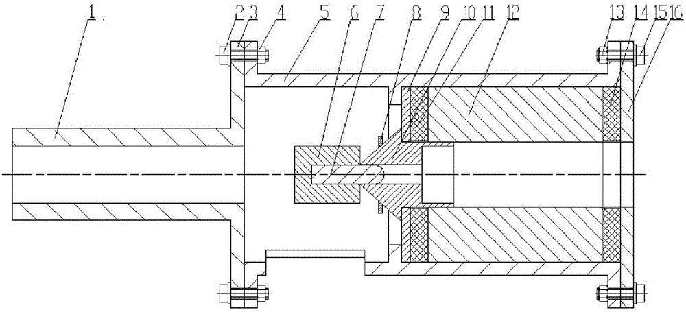
[0024] Comply with the above technical solutions, such as figure 1 , Figure 4 — Figure 6As shown, the first preferred embodiment of the present invention includes a bracket 5 , a separator 12 , a deceleration ring 8 , a backing plate 9 , a first rubber cushion 11 , an inert body 12 , a second rubber cushion 14 and a baffle 16 . The support 5 is a steel cylinder with a boss processed on the inner wall. The two ends of the cylinder are respectively equipped with a second flange 5-1 and a third flange 5-3. The second flange 5 -1 and the third flange 5-3 are respectively provided with 6 uniformly distributed through holes 5-4, and the support 5 passes through the through holes on the second flange 5-1 and the third flange 5-3 5-4 Use the first screw 2, the first nut 4, the second screw 13 and the second nut 15 to connect with the flange 3 and the baffle plate 16 on the gun barrel 1 respectively; There are three evenly distributed vent holes 5-2 on the circumference, the size ...

Embodiment 2

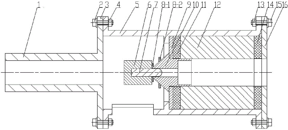
[0037] The overall structure and the material of the projectile support separation device under the high-speed impact of the large-mass projectile are the same as that of Embodiment 1. The difference between the second preferred embodiment and the first preferred embodiment is that in order to enable the present invention to operate at a higher speed ( greater than 500m / s) to realize the complete separation of projectile and bullet holders. Two deceleration rings are installed on the separator 10, which are respectively the first deceleration ring 8-1 and the second deceleration ring 8-2, and the first deceleration ring 8-1 and the second deceleration ring 8-2. The distance between the second deceleration ring 8-2 and the conical mouth of the separator 10 is respectively 0mm, 1 / 2 the conical length, the diameter of the first deceleration ring 8-1 and the second deceleration ring 8-2 is the largest with the central variable diameter hole The aperture ratio is 2.5:1, the thicknes...

Embodiment 3

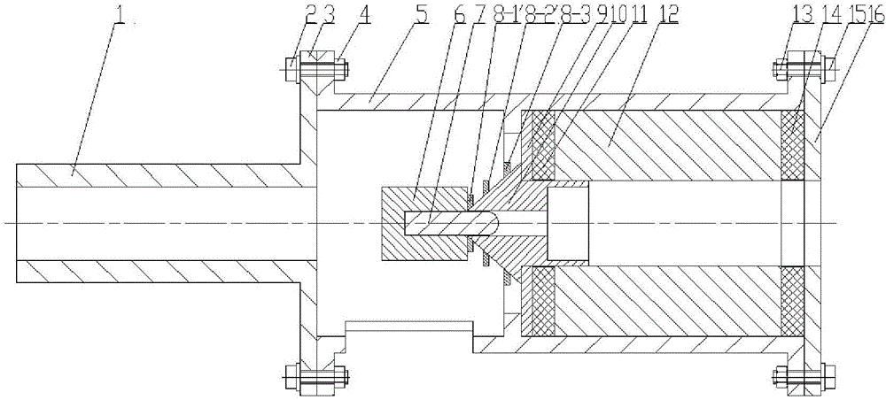
[0043] The overall structure and the material of the projectile carrier separation device under the high-speed impact of the large-mass projectile are the same as in Embodiment 1. The difference between the third preferred embodiment and the first preferred embodiment is that in order to enable the present invention to operate at a higher speed ( greater than 550m / s) to realize the complete separation of projectiles and projectile supports, three deceleration rings are installed on the separator 10, which are respectively the third deceleration ring 8-1', the fourth deceleration ring 8-2' and the fifth deceleration ring 8-3, The distances between the third deceleration ring 8-1', the fourth deceleration ring 8-2', the fifth deceleration ring 8-3 and the conical mouth of the separator 10 are respectively 0mm, 1 / 3 conical length and 1 / 3 conical Shape length, the ratio of the diameter of the third deceleration ring 8-1', the fourth deceleration ring 8-2' and the fifth deceleration...


PUM


Abstract

The invention discloses a projectile and projectile support separating device under high-speed impacts of a large-mass projectile. The projectile and projectile support separating device comprises a support, a separator, a speed reduction ring, a cushion plate, a buffering rubber pad, an inertia body and a baffle. The support is a cylinder with the two ends provided with flange plates and a boss machined on the inner wall. The support is connected with a flange plate on a gun barrel and the baffle through the flange plates. The separator, the cushion plate, the buffering rubber pad and the inertia body are arranged in the support. The end, facing the gun barrel, of the separator is in a conical shape, the other end of the separator is in a cylindrical shape, and the separator is provided with a penetrating step type center through hole. The outer circumference of the conical end of the separator is sleeved with the speed reduction ring, and the cylindrical end is positioned through a center through hole in the cushion plate. The projectile and projectile support separating device has the beneficial effects that the strong impact load can be borne, the time of the reverse impact load acting on a projectile support can be prolonged, the requirement for separation of the projectile and the projectile support under the high impact speed of the large-mass projectile is met, the additional damage of a target due to the impact of the projectile support on a target plate is effectively avoided, and repeated usage can be achieved.

Description

technical field [0001] The invention belongs to the technical field of high-speed collision laboratory test devices, and relates to a projectile and carrier separating device, in particular to a projectile and carrier separating device for a large-mass projectile launching device. Background technique [0002] Light gas cannon is one of the most commonly used technologies for dynamic high-pressure loading at present. It can launch projectiles of various shapes, and the quality, size and material of projectiles have a wide range of application. Compared with the second-level light gas gun, the first-level light gas gun is easy to operate and has a large caliber, and can load large-mass projectiles (5-7kg) to more than 400m / s, so it is often used in various scale penetration battles The study of the internal penetration mechanism. Due to the limitation of projectile shape and length-to-diameter ratio, etc., it is generally necessary to adopt sub-caliber launch technology, tha...

Claims


Application Information

Patent Timeline
IPC IPC(8): F42B10/00F42B10/02
CPCF42B10/00F42B10/02
Inventor 屈可朋沈飞李亮亮何超王辉肖玮
Owner XIAN MODERN CHEM RES INST
Why Eureka
Try Eureka