A fuel jet flow concentration field distribution testing device and an implementing method thereof

A technology of distribution testing and concentration field, applied in measurement devices, material excitation analysis, material analysis by optical means, etc., can solve the problem of large uncertainty of calibration method, reduce the difficulty of operation and calculate the uncertainty of calibration coefficient K, PLIF Difficulty in operation, etc.

Active Publication Date: 2016-09-28
浙江和夏科技股份有限公司
View PDF4 Cites 12 Cited by
  • Summary
  • Abstract
  • Description
  • Claims
  • Application Information

AI Technical Summary

Problems solved by technology

[0003] In order to solve the problems that the traditional PLIF is difficult to operate and the calibration method is uncertain, the present invention provides an implementation device for testing the concentration field distribution of fuel jets, and uses the device to invent a method for testing the concentration field distribution of fuel jets , this method adds trace...

Method used


Image

  • A fuel jet flow concentration field distribution testing device and an implementing method thereof

Examples


specific Embodiment approach 2

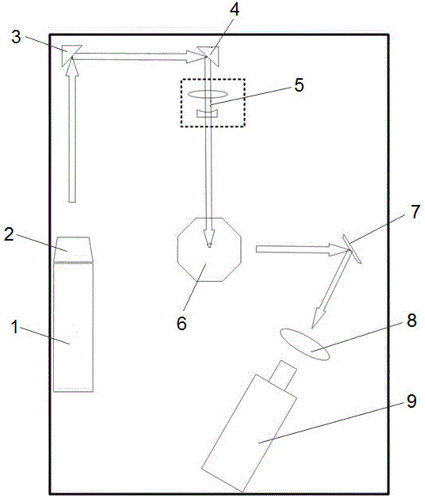
[0020] Embodiment 2. This embodiment is a further description of the fuel jet concentration field distribution test device described in Embodiment 1. Fuel is injected in the constant volume bomb system 6, and the atmosphere charged in the constant volume bomb system 6 is an inert gas. , the atmosphere is filled with tracer particles, and the tracer particles are organic compounds.

[0021] Further, acetone can be selected as the tracer particles.

specific Embodiment approach 3

[0022] Embodiment 3. This embodiment is a further description of the fuel jet concentration field distribution testing device described in Embodiment 1. The laser 1 is a Nd:YAG laser.

specific Embodiment approach 4

[0023] Embodiment 4. This embodiment is a further description of the fuel jet concentration field distribution testing device described in Embodiment 1. The fluorescent signal detector 9 adopts an ICCD camera.


PUM


Abstract

A fuel jet flow concentration field distribution testing device belonging to the technical field of concentration field testing and an implementing method thereof are disclosed. The device comprises a laser, a frequency doubler, total reflection prisms, a disk laser generating lens group, a constant volume bomb system, a plane mirror, a filter mirror and a fluorescence signal detector. The device generates collimating laser signals by adopting the laser, collimating laser signals of a corresponding wavelength are obtained through the frequency doubler, the light path is changed through the first and second total reflection prisms so as to allow entrance into the disk laser generating lens group, collimating light is converted into disk light through the disk laser generating lens group, the disk light is emitted into a constant volume bomb to induce tracer particles to generate fluorescence, the fluorescence is captured through the fluorescence signal detector to generate a two-dimension fluorescence image after the light path of the fluorescence is changed through the plane mirror and the fluorescence is then filtered through the filter mirror, the generated image is divided into n grids, and the quantitative fuel mist concentration distribution is obtained by numerical calculation through a correlation between calibrated concentrations and light intensity. Test conditions of the device and the method are close to those of practical internal combustion engines. The device and the method have guiding significance for future internal combustion engine development.

Description

technical field [0001] The invention relates to a test device in the technical field of concentration field test, in particular to a test device for concentration field distribution of fuel jet by laser-induced fluorescence method and an implementation method thereof. Background technique [0002] In recent years, in the development of internal combustion engine technology, in order to better control fuel combustion efficiency and emissions, the concentration distribution field of fuel spray before internal combustion engine combustion is very important. If the concentration of fuel spray can be quantitatively determined The distribution has a good reference value for spray control and combustion chamber design. Compared with the probe method, the optical diagnosis method of the internal combustion engine has the advantage of not disturbing the local flow field, especially the planar laser-induced fluorescence (PLIF) method can quantitatively display the concentration distri...

Claims


Application Information

Patent Timeline
IPC IPC(8): G01N21/64
CPCG01N21/6402
Inventor 李铁史卫全
Owner 浙江和夏科技股份有限公司
Why Eureka
Try Eureka