Method and apparatus for wavefront measurement that resolves the 2-pi ambiguity in such measurement and adaptive optics systems utilizing same

a wavefront and ambiguity technology, applied in the field of wavefront sensors, can solve problems such as large phase step measurement errors, blue images, and sensitive shack-hartmann methods

Inactive Publication Date: 2005-05-12
NORTHROP GRUMMAN SYST CORP
View PDF25 Cites 21 Cited by
  • Summary
  • Abstract
  • Description
  • Claims
  • Application Information

AI Technical Summary

Benefits of technology

[0011] Accordingly, a primary object of the present invention is to provide an improved wav

Problems solved by technology

Although twinkling stars are pleasant to look at, the twinkling causes blurring on an image obtained through a telescope.
Since the reference wave suffers no atmospheric distortion, any displacement of the reference wave's subaperture spot position from that of the subaperture's chief ray is attributable to sensor distortion.
However, the Shack-Hartmann method is sensitive to a phase step across the subaperture.
Importantly, this 2π ambiguity leads to measurement errors for large phase steps.
As described above, the Schac

Method used


Image

  • Method and apparatus for wavefront measurement that resolves the 2-pi ambiguity in such measurement and adaptive optics systems utilizing same
  • Method and apparatus for wavefront measurement that resolves the 2-pi ambiguity in such measurement and adaptive optics systems utilizing same
  • Method and apparatus for wavefront measurement that resolves the 2-pi ambiguity in such measurement and adaptive optics systems utilizing same

Examples


Embodiment Construction

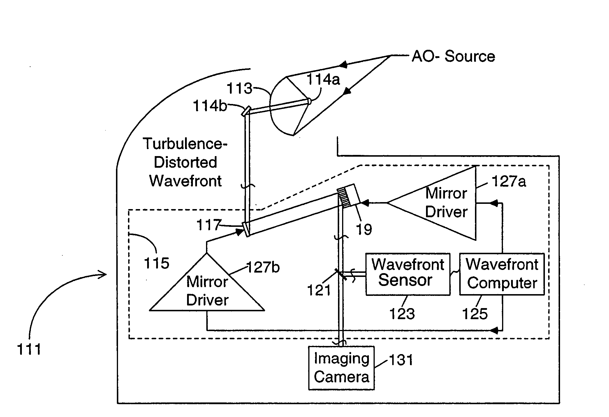
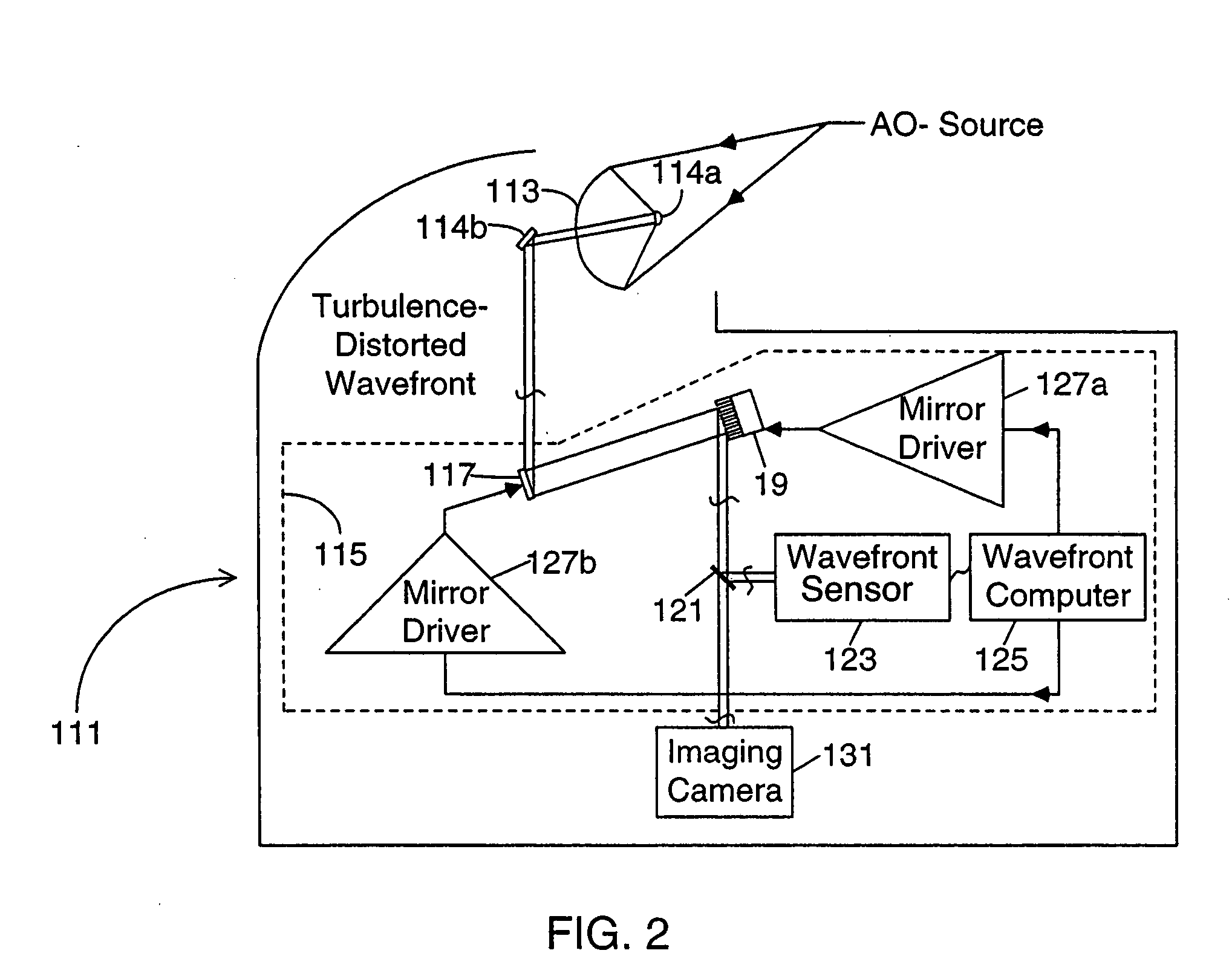
[0046] Referring to the figures in the accompanying Drawings, the preferred embodiments of the Planar Laser Illumination and (Electronic) Imaging (PLIIM) System of the present invention will be described in great detail, wherein like elements will be indicated using like reference numerals. In FIG. 2, there is shown an adaptive optics based large-aperture space telescope 111 embodying the adaptive optics subsystem 115 of the present invention which is capable of measuring and correcting large wavefront phase errors free of 2π phase resolution ambiguity.

[0047] As shown in FIG. 2, light from a nominal point source above the atmosphere enters the primary mirror 113 of the telescope 111 and is focused and directed by mirrors 114A and 114B to an adaptive optics subsystem 115. The adaptive optics subsystem 115 includes a tilt mirror 117 and a deformable mirror 19 disposed between its source (the mirrors 114A and 114B) and an electronic imaging camera 131. A beam splitter 121 directs a po...


PUM


Abstract

An improved wavefront sensor for characterizing phase distortions in incident light including optical elements that spatially sample the incident light and form a dispersed spot with a fringe pattern corresponding to samples of the incident light. An imaging device captures an image of the dispersed spot with said fringe pattern formed by said optical elements. And an image processor that analyzes the spectral components of the fringe pattern of a given dispersed spot to derive a measure of the local phase distortion without ambiguity in the corresponding sample of incident light. The optical elements may comprise refractive elements, diffractive elements or a combination thereof (such as a grism). The wavefront sensor may be part of an adaptive optic system (such as a large-aperture space telescope) to enable the measurement and correction of large phase steps across adjacent mirror segments of a deformable mirror.

Description

CROSS-REFERENCE TO RELATED APPLICATIONS [0001] This application claims priority from U.S. Provisional Application Ser. No. 60 / 218,190 filed Jul. 14, 2000, and U.S. Application Ser. No. 09 / 766,211 filed Jan. 19, 2001, herein incorporated by reference in their entirety.FIELD OF THE INVENTION [0002] This invention relates to wavefront sensors that measure and characterize the phase error in wavefronts, and adaptive optics systems, such as large aperture space telescopes, that utilize wavefront sensors to measure and compensate for phase errors (caused primarily by atmospheric turbulence) in the wavefronts captured therein, thereby overcoming the blurring in images that would otherwise be caused by such phase errors. BACKGROUND OF THE INVENTION [0003] An adaptive optics system automatically corrects for light distortions in the medium of transmission. For example, if you look far down a road on a very hot and sunny day, you will often see what is usually called a mirage. What you are se...

Claims


Application Information

Patent Timeline
IPC IPC(8): G01J9/00
CPCG01J9/00G02B26/06G01J9/02
Inventor WIRTH, ALLAN
Owner NORTHROP GRUMMAN SYST CORP
Why Eureka
Try Eureka