

Amplitude weighting-based ground penetrating radar back projection imaging method
A ground-penetrating radar and back-projection technology, applied in the field of radar imaging, can solve problems such as poor imaging results, hyperbolic inability to focus, affecting target detection and positioning, etc., and achieve the effect of improving accuracy and suppressing ability
- Summary
- Abstract
- Description
- Claims
- Application Information
AI Technical Summary
Problems solved by technology
Method used
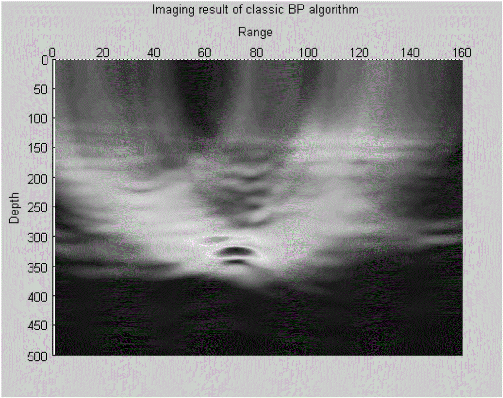
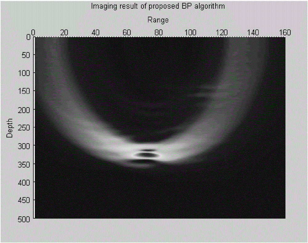
Image

Examples
specific Embodiment approach 1
[0026] The ground-penetrating radar back projection imaging method based on amplitude weighting in this embodiment, combined with Figure 6 The flow chart of described method is realized through the following steps:
[0027] Step 1. Set the total number of channels of the ground penetrating radar as M, and calculate the round-trip time delay from any imaging point A to each channel in the imaging area. Then, the round-trip time delay τ from imaging point A to the kth channel A,k Expressed as:
[0028] τ A , k = 2 ( x k - x A ) 2 ...
specific Embodiment approach 2
[0036] The difference from Embodiment 1 is that in the amplitude-weighted GPR backprojection imaging method of this embodiment, the process of calculating the scattering response amplitude of imaging point A in each channel described in step 2 is as follows. The echo of each channel of the ground radar is r k (t) means, and then get the scattering response amplitude x of imaging point A in each channel A,k x respectively A,k = r k (t), t=τ A,k ; In the formula, k represents the channel number, and k=1,2,...,M.
specific Embodiment approach 3
[0037] The difference from the specific embodiment 1 or 2 is that, in the amplitude-weighted ground-penetrating radar back-projection imaging method based on the amplitude weighting of this embodiment, the process of constructing the window function W described in step 3 is as follows:
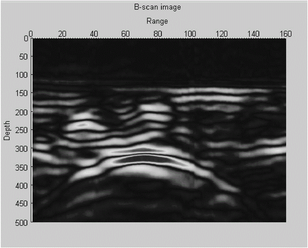
[0038] Step 31. Set the horizontal area of the hyperbola to correspond to m channels, respectively k 1 ,k 2 ,...,k m ; Edge extraction is performed on the obtained ground-penetrating radar B-scan image, and the response amplitudes corresponding to the points on the hyperbola are respectively u 1 ,u 2 ,..., u m , and construct a 1×M-dimensional vector W', and:
[0039]
[0040] Among them, M represents the total number of channels, and m represents the number of channels occupied by the ground-penetrating radar echo hyperbolic horizontal area;
[0041] Step 32, set the total channel number M and the channel number m corresponding to the hyperbola to be even numbers,
[0042] Step 33:...
PUM
 Abstract
Description
Claims
Application Information