
A high-power memristor circuit realized by spwm control

A memristor and high-power technology, applied in the field of high-power memristor circuits, can solve problems such as power limitation and inapplicability to power electronic circuits, and achieve the effects of continuous output current and simple circuit structure

Active Publication Date: 2018-10-09
SOUTH CHINA UNIV OF TECH
View PDF9 Cites 0 Cited by
  • Summary
  • Abstract
  • Description
  • Claims
  • Application Information

AI Technical Summary

Problems solved by technology

[0005] In 2008, Hewlett-Packard produced a nanoscale memristor, but the memristor is mainly used for computer storage, not suitable for power electronic circuits
Most of the existing memristor models are low-power models, which are built from multipliers, operational amplifiers and other devices, and their power is limited to a certain extent.

Method used


Image

  • A high-power memristor circuit realized by spwm control
  • A high-power memristor circuit realized by spwm control
  • A high-power memristor circuit realized by spwm control

Examples


Embodiment

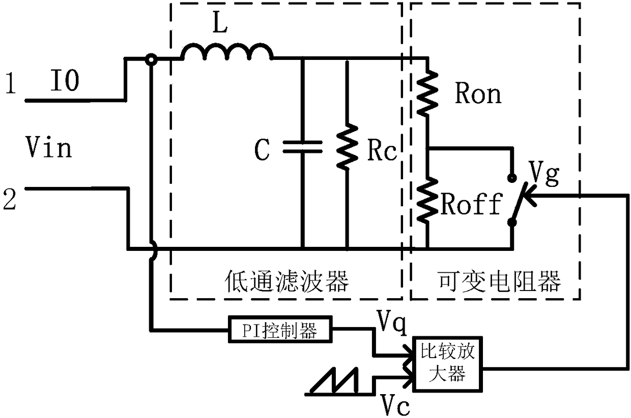
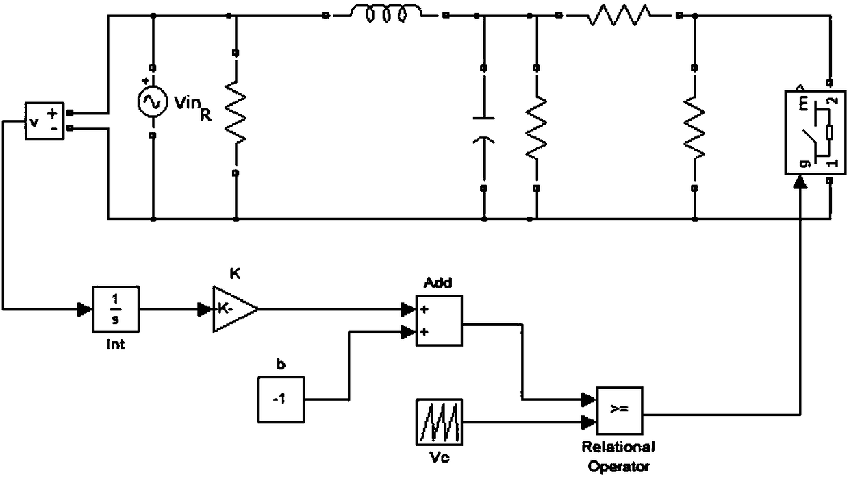
[0036] Such as figure 1 , a specific structure of a high-power memristor circuit realized by using SPWM and a filter circuit is as follows: the first end of the input end (that is, the "1" end) is connected to one end of the inductance L, the other end of the inductance L is connected to one end of the capacitor C, One end of the resistor Rc is connected to one end of the resistor R1, the other end of the resistor R1 is connected to one end of the resistor R2, and one end of the switch tube is connected, the other end of the resistor R2 is connected to the second end of the input terminal (that is, the "2" end), and the capacitor C The other end, the other end of the resistor Rc, is connected to the other end of the switch tube. The input voltage Vin is sampled and transmitted to the PI controller (proportional-integral controller), and then the modulated wave Vq is obtained. The modulated wave Vq and the carrier signal Vc are compared and amplified to obtain the pulse voltage...


PUM


Abstract

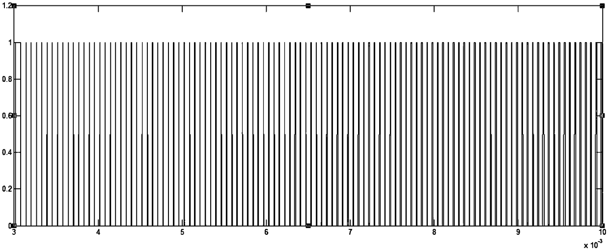
The invention discloses a high-power memristor circuit realized by virtue of SPWM control. The high-power memristor circuit comprises an inductor L, a capacitor C, a resistor Rc, a resistor Ron, a resistor Roff, a thyristor, a PI controller and a comparison amplifier, wherein the inductor L makes current continuous and forms a low pass filter with the capacitor C and the resistor Rc so as to realize the same phase between input voltage and output current; the PI controller integrates the input voltage to obtain a magnetic flux variable, the comparison amplifier makes comparison between the magnetic flux variable and a triangular carrier to obtain an SPWM waveform, and the thyristor and the resistor Roff are connected in parallel to form a variable resistor with a controllable SPWM waveform. According to the high-power memristor circuit, by virtue of the SPWM waveform, the resistance value of the variable resistor is changed to conform to the properties of the resistance value of the memristor; by utilizing the power devices such as the inductor, the capacitor and the thyristor, the circuit structure is simple, and the thyristor with any power level can be theoretically realized; by utilizing the low pass filter, the output current is continuous and has the same phase with the input voltage.

Description

technical field [0001] The invention relates to the technical field of power electronics, in particular to a high-power memristor circuit realized by SPWM control. Background technique [0002] The memristor is a basic component with memory characteristics proposed by the Chinese scientist Cai Shaotang. It is divided into a magnetron memristor and a charge-controlled memristor. The definition of the magnetron memristor is: [0003] [0004] Its basic characteristic is that when a sine wave signal is input, the volt-ampere characteristic curve of the memristor is a "slope". [0005] In 2008, Hewlett-Packard produced a nanoscale memristor, but the memristor is mainly used for computer storage, not suitable for power electronic circuits. Most of the existing memristor models are low-power models, which are built from multipliers, operational amplifiers and other devices, and their power is limited to a certain extent. [0006] Connect the switch tube and the resistor in pa...

Claims


Application Information

Patent Timeline
Patent Type & Authority Patents(China)
IPC IPC(8): G11C13/00
CPCG11C13/0069
Inventor 陈艳峰谭斌冠张波
Owner SOUTH CHINA UNIV OF TECH
Learn More