Large-power xenon lamp bulb and preparation method thereof

A high-power, xenon technology, applied in the field of xenon lamps, can solve the problems of loss of light source, affecting luminous efficiency, affecting service life, etc., to achieve the effects of uniform and controllable thickness, uniform surface temperature, and smooth surface

Inactive Publication Date: 2016-09-28
GUANGDONG CHANGSHENG LIGHTING TECH +1
9 Cites 5 Cited by

AI-Extracted Technical Summary

Problems solved by technology

Although the patented structure and process are not complicated, the biggest disadvantage is that the connection of the exhaust pipe cannot be achieved, and the thickness cannot be guaranteed to be consistent with other wall thicknesses, which may easily lead to uneven heating and excessive high temperature at the connection be...

Abstract

The invention discloses a large-power xenon lamp bulb and a preparation method thereof. The large-power xenon lamp bulb comprises a bulb casing, the two sides of the bulb casing are each provided with a glass tube, the glass tubes are internally provided with molybdenum rods with molybdenum sheets, and the bulb casing is filled with xenon, a metal halide and mercury. The large-power xenon lamp bulb is characterized in that the glass tubes are provided with clamping sealing positions for fixing the molybdenum rods, and each molybdenum rod is provided with a limiting lamp pin abutting against the inner walls of the two sides of each glass tube. The structure is simple, the processing is convenient, the product surface temperature during work is uniform, the life is long, 360-degree light extraction is uniform, the transmittance is good, and the performance is better.

Application Domain

Technology Topic

Image

  • Large-power xenon lamp bulb and preparation method thereof
  • Large-power xenon lamp bulb and preparation method thereof
  • Large-power xenon lamp bulb and preparation method thereof

Examples

  • Experimental program(1)

Example Embodiment

[0027] The technical solution will be described in detail below in conjunction with specific embodiments.
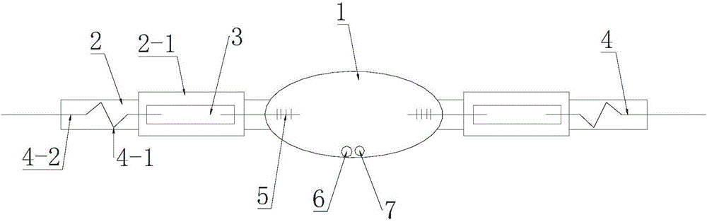
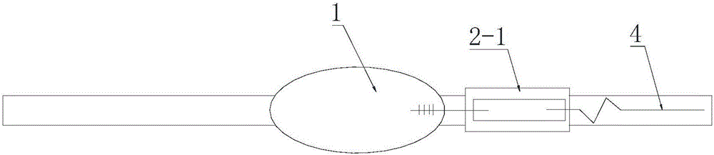
[0028] Such as figure 1 As shown, the present invention is a high-power xenon bulb, which includes a bulb 1 which is an olive-shaped glass bulb. A glass tube 2 is provided on both sides of the bulb 1 respectively. The glass tube 2 is provided with a molybdenum rod 4 with a molybdenum sheet 3, and the end of the molybdenum rod 4 is provided with an electrode tip 5, and the bulb is filled with xenon gas and metal halide The glass tube 2 is provided with a clamping position 2-1 for fixing the molybdenum rod, and the molybdenum rod is provided with limit lamp pins 4-1 pressed against the inner walls of both sides of the glass tube. The limit lamp pin 4-1 includes an S-shaped support bent by a molybdenum rod. The two ends of the S-shaped support are respectively pressed against the inner wall of the glass tube. The end of the limit lamp pin has a straight rod extending out of the glass tube. Section 4-2. Of course, the S-shaped support can also be replaced with other shapes of support and positioning structures, such as T-shaped, V-shaped, etc., in order to make the position of the molybdenum rod on the central axis of the glass tube.
[0029] The clamping position 2-1 is arranged between the glass tube and the limit lamp pin, the clamping position is flat, and the bulb is an olive-shaped glass bulb.
[0030] The following is the preparation method corresponding to the high-power xenon bulb, which includes the following steps:
[0031] a. Prepare the bubble body, select a quartz glass tube of appropriate length, and blow the middle part into an olive-shaped bubble shell through a bubble blowing machine, such as figure 2;
[0032] b. Then insert a first molybdenum rod with a limited lamp pin into one side of the glass tube of the blister, place the electrode end of the first molybdenum rod in the blister, clamp and seal tightly at the molybdenum sheet, such as image 3;
[0033] c. Put the blister with one end of the electrode in a vacuum high temperature furnace, and vacuum dehydroxylation in a 1000-1100 degree high temperature furnace for 7-10 hours;
[0034] d. After cooling the dehydroxylated bulb, add metal halide and mercury to the bulb through the unsealed end of the glass tube;
[0035] e. Insert the second molybdenum rod with a limited lamp pin into the other side of the unsealed blister glass tube, confine it in a proper position, and then fix it on a clamping machine or plasma flame seal, such as Figure 4;
[0036] f. The unsealed end is filled with xenon gas into the bulb, and after the xenon gas is filled, the tube mouth is clamped and sealed by a clamp sealer or plasma flame seal, and then the molybdenum rod at the end is clamped and sealed;
[0037] g. Cut the end of the glass tube flat with a tube cutter at both ends, exposing a molybdenum rod of appropriate length to obtain a high-power xenon bulb product, such as figure 1.
[0038] Further, the length of the molybdenum rod protruding from the glass tube is 3-30 mm. In the e step, the distance between the electrode ends of the two molybdenum rods needs to be adjusted. The process is to insert the second molybdenum rod into the glass tube on the other side of the unsealed blister, and then put the whole into the projector In the object placement area, adjust the focus of the projector to a clear state, and adjust the electrode distance to a symmetrical electrode distance of 25-180mm according to different power requirements. The specific process of dehydroxylation of the blister shell is: first clean the surface of the blister shell with a dust-free cloth sticking absolute ethanol, and dry it; then put the dried blister shell into the glove box, and place the arc in the glove box. The tube is placed in a quartz container, and then the quartz container is placed in a high-temperature furnace for vacuum dehydroxylation.
[0039] Compared with the prior art, the present invention is simpler in process and higher in production efficiency; in terms of products, the entire foam body has a smooth surface, a uniform and controllable thickness, and an overall beautiful appearance. When working, the surface temperature is uniform, and the service life is 10% longer than that of a traditional bulb with an exhaust pipe; the 360-degree light output is uniform, and the light transmission is good, which is more than 10% higher than that of a traditional bulb with an exhaust pipe.
[0040] The above are only the preferred embodiments of the present invention. It should be pointed out that for those of ordinary skill in the art, without departing from the inventive concept of the present invention, several modifications and improvements can be made, all of which belong to the present invention. The scope of protection of the invention.

PUM

PropertyMeasurementUnit
Length3.0 ~ 30.0mm
tensileMPa
Particle sizePa
strength10

Description & Claims & Application Information

We can also present the details of the Description, Claims and Application information to help users get a comprehensive understanding of the technical details of the patent, such as background art, summary of invention, brief description of drawings, description of embodiments, and other original content. On the other hand, users can also determine the specific scope of protection of the technology through the list of claims; as well as understand the changes in the life cycle of the technology with the presentation of the patent timeline. Login to view more.

Similar technology patents

Classification and recommendation of technical efficacy words

  • Flat surface
  • Uniform and controllable thickness

Reinforced aerogel composite material and preparation method thereof

ActiveCN104496403AFlat surfaceGood flexural resistanceThermal insulationEnergy absorption
Owner:NANJING WEICAI NEW ENERGY TECH

Low-temperature low-pressure preparation method of boron nitride coating

InactiveCN105669253AStrong penetration abilityUniform and controllable thicknessChemical vapor deposition coatingBoron nitrideBoron trichloride
Owner:SHANGHAI UNIV +1

Method for synthesizing lithium ion battery positive electrode material

InactiveCN105206821AUniform and controllable thicknessReduce exposureMaterial nanotechnologyCell electrodesLanthanum nitrateLithium electrode
Owner:SHANGHAI ELECTRICGROUP CORP +1

Copper thin film preparation method

ActiveCN108220924AUniform physical propertiesUniform and controllable thicknessLiquid/solution decomposition chemical coatingCopper thin filmNanoscopic scale
Owner:TECHNICAL INST OF PHYSICS & CHEMISTRY - CHINESE ACAD OF SCI
Why Eureka
Try Eureka