
A Space Multiplexing Method for Directional Antennas in Millimeter Wave Systems

A technology of spatial multiplexing and directional antennas, applied in transmission systems, spatial transmit diversity, radio transmission systems, etc., can solve the problems of inaccurate determination of interference signals, time-consuming, etc., to improve spatial multiplexing gain, reduce detection time, The effect of increasing throughput

Active Publication Date: 2019-05-31
SOUTHEAST UNIV
View PDF3 Cites 0 Cited by
  • Summary
  • Abstract
  • Description
  • Claims
  • Application Information

AI Technical Summary

Problems solved by technology

However, this method also has some shortcomings: (1) The receiving end of other devices needs to receive signals omnidirectionally. When a directional antenna is used, it will cause inaccurate judgment of interference signals
(2) The device needs to use all devices as a source device to detect and scan each sector to record the sector listening table before the signal transmission period, which takes extra time
This patent application only focuses on the hardware aspect, which effectively reduces the cost of efficiency, and does not involve the gain of spatial multiplexing in resource allocation.

Method used

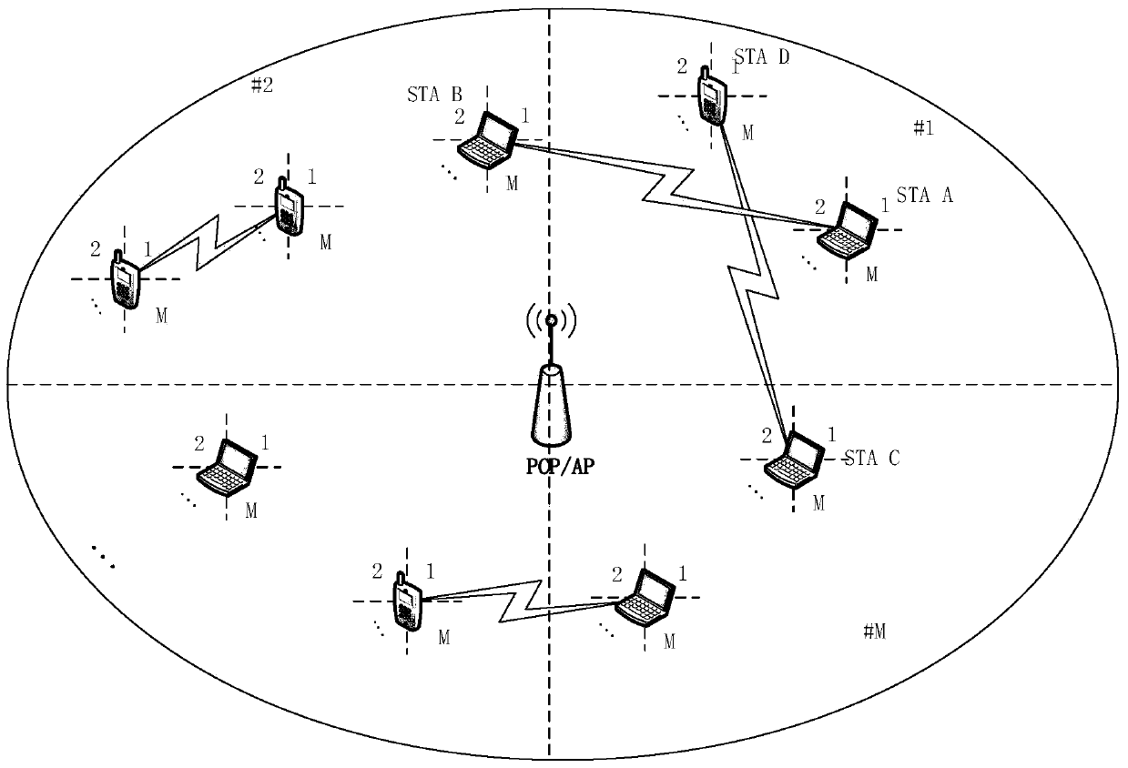
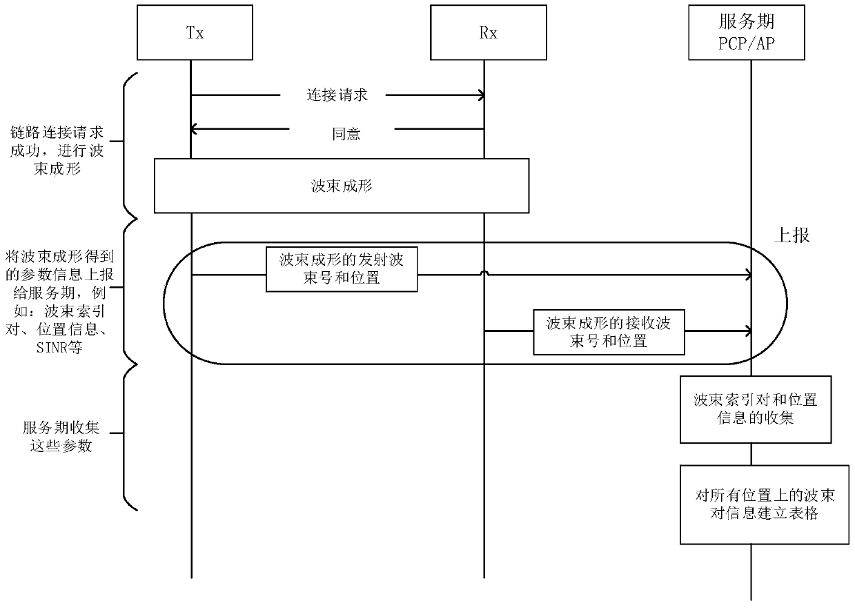
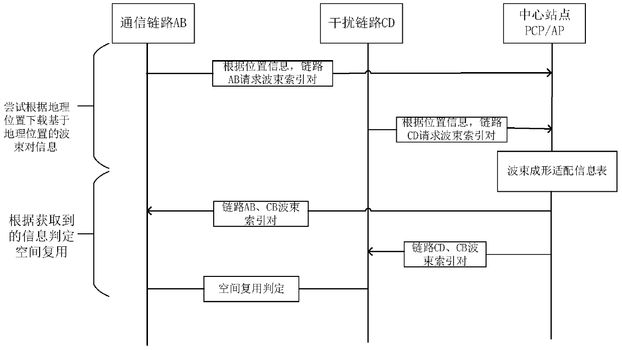

Image

  • A Space Multiplexing Method for Directional Antennas in Millimeter Wave Systems
  • A Space Multiplexing Method for Directional Antennas in Millimeter Wave Systems
  • A Space Multiplexing Method for Directional Antennas in Millimeter Wave Systems

Examples


Embodiment Construction

[0037] Below in conjunction with specific embodiment, further illustrate the present invention, should be understood that these embodiments are only used to illustrate the present invention and are not intended to limit the scope of the present invention, after having read the present invention, those skilled in the art will understand various equivalent forms of the present invention All modifications fall within the scope defined by the appended claims of the present application.

[0038] First of all, since there is no specific spatial multiplexing information collection mechanism and evaluation criteria in the existing standards, the information collection mechanism is now defined as follows: Since the main factors affecting millimeter wave communication, multipath and propagation loss depend on the location of the terminal , therefore, reusing existing beam index pairs at the same position can reduce a lot of time for repeated calculations. When the link performs beamform...


PUM


Abstract

The invention discloses a direction antenna spatial multiplexing method for a millimeter wave system. Firstly, an information collection mechanism and evaluation criteria are defined, and then the following steps are carried out. The steps comprise 1, feeding back beam reference pairs of a transmitting and receiving end to a PCP / AP in a beam forming process, thereby forming a beam reference pair information table BFT; 2, transforming the beam reference pair information table BFT into a link beam difference value table LDT; 3, performing a spatial multiplexing dispatching algorithm, and generating an optimum link dispatching method; and 4, sending a generation scheme to each STA by the PCP / AP through BTI, and performing the generation scheme in a next SP period by the STA. According to the method, the detection time of signal interference between links is reduced, the simple, easy-judging and effective evaluation criteria are designed, the feasible, fast and effectively dispatching scheme is provided, the spatial multiplexing gain can be effectively improved, and the throughput of the whole millimeter wave system can be improved.

Description

technical field [0001] The invention relates to a space multiplexing method for transmitting and receiving beam index pairs in the millimeter wave beam forming process, and belongs to the technical field of wireless communication. Background technique [0002] Millimeter wave (mmWave) communication technology has always been a hot topic of common concern in academia, industry, and standard circles. In recent years, the US Federal Communications Commission (FCC) has considered authorizing LMDS frequency bands (27.5GHz-28.35GHz, 29.1GHZ-29.25GHz, 31GHZ-31.3GHz), 32GHz frequency bands, 39GHz frequency bands, 37GHz-41GHz frequency bands and 60GHz frequency bands for future use E-Band (70GHz-80GHz) can provide continuous bandwidth (1-2GHz), meeting the requirements of 10Gbit / s peak rate and 100Mbit / s-1Gbit / s cell edge rate in 5G technology. One of the dynamic technologies of "industry attractiveness". Major standard organizations have continuously introduced drafts and standard...

Claims


Application Information

Patent Timeline
Patent Type & Authority Patents(China)
IPC IPC(8): H04B7/0417H04B7/06H04B7/08
CPCH04B7/0417H04B7/0617H04B7/086
Inventor 徐平平王潍潍徐一成
Owner SOUTHEAST UNIV
Learn More