Coastal wetland surface elevation dynamic change and aggradation speed measurement method

A surface elevation and dynamic change technology, applied in the field of height measurement, can solve the problems affecting the dynamic monitoring of the wetland surface, the inability to obtain the deposition erosion thickness of the horizontal marker layer, and the complex dynamic environment, etc., to achieve wide application range, simple preparation process, and data accurate effect

Active Publication Date: 2016-10-05
QINGDAO INST OF MARINE GEOLOGY
View PDF4 Cites 6 Cited by
  • Summary
  • Abstract
  • Description
  • Claims
  • Application Information

AI Technical Summary

Problems solved by technology

Coastal wetlands are located in the land-sea interaction zone, and the dynamic environment is complex, especially the tidal flats of coastal wetlands. In many places, the sediments

Method used


Image

  • Coastal wetland surface elevation dynamic change and aggradation speed measurement method
  • Coastal wetland surface elevation dynamic change and aggradation speed measurement method

Examples


Embodiment 1

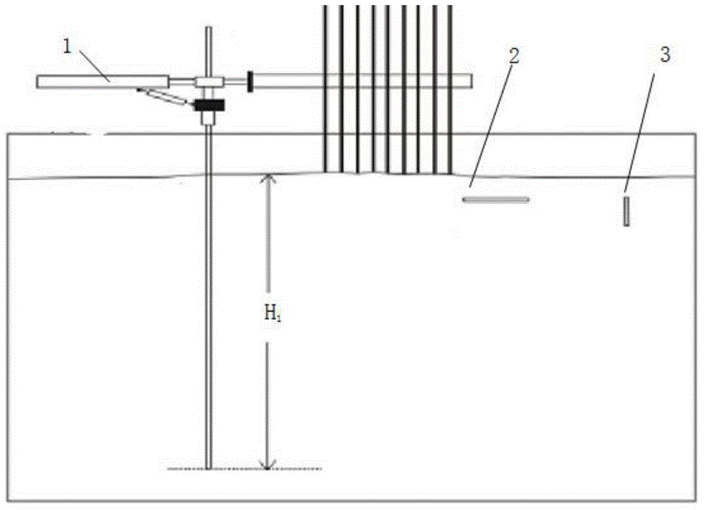
[0039] as per figure 1 In the described method, the surface elevation measuring instrument 1, the horizontal marking layer 2 and the dyed sand stick 3 are placed.

[0040] The level marking layer 2 can be colorless or colored sand, brick ash, fluorescent powder, feldspar powder, solid polyester resin layer or filter paper.

[0041] Described dyed sand stick 3 adopts following method to make: 1. get the beach loose sand 10kg of point to be tested, fluorescein (fluorescein) 20g, agar powder 10g; 2. the beach sand that gets is washed several times with fresh water, 3. Stir the fluorescein and the dried sand according to the proportion evenly; 4. Put 10g of agar in water at 2500°C and boil to dissolve the agar completely, remove the heat, and cool down to below 50 degrees Celsius; 5. Stir the cooled agar solution and the stirred sand evenly (until there is no dry sand), and dry it in the shade for later use; 6. Make the sand dried in the shade into a dyed sand stick with a height...

Embodiment 2

[0051] This embodiment has the same structure as Embodiment 1 except the following features:

[0052] The measurement method can be used to measure dynamic changes in surface elevation, surface erosion rate, and soil subsidence rate measurement below the surface, including the following steps:

[0053] (1) Fix the surface elevation measuring instrument at the measuring point;

[0054] (2) Place a horizontal marker layer at the measurement point;

[0055] (3) Place a vertical dyed sand rod at the measurement point, and the top of the dyed sand rod coincides with the deposition surface;

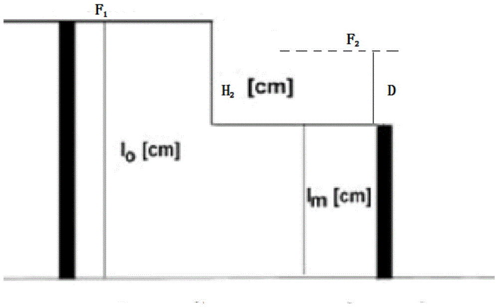
[0056] (4) After a period of time t, read the surface elevation measuring instrument to obtain the surface elevation change S 2 ;

[0057] (5) Then measure the remaining length of the dyed sand rod to obtain the reduced length H of the dyed sand rod 2 is the thickness of the eroded sediment, H 2 =I 0 -I m ;

[0058] (6) Measuring the erosion final interface F 2 The distance D from the to...


PUM

PropertyMeasurementUnit
Lengthaaaaaaaaaa
Heightaaaaaaaaaa
Lengthaaaaaaaaaa

Abstract

The invention belongs to the field of elevation measurement methods and particularly relates to a coastal wetland surface elevation dynamic change and aggradation speed measurement method which is used for measuring a surface aggradation region or erosion region and includes the steps of: (1) fixing a surface elevation measuring instrument at a measurement point; (2) arranging a level mark layer on the measurement point; (3) arranging a vertical dyed sand rod at the measurement point, wherein the top of the sand rod is coincided with a depositional surface; and (4) after a certain time t, reading the surface elevation measuring instrument to acquire surface elevation change S. Compared with the prior art, the method is suitable for surface elevation measurement in a coastal wetland complex region and is not liable to lose in measurement capability just because erosion. The method can achieve the surface elevation measurement no matter how the surface elevation is changed in height, so that the method has a wider application range and more accurate data results. Preparation of the dyed sand rod is simple, economical and convenient.

Description

technical field [0001] The invention belongs to the field of height measurement methods, and in particular relates to a method for measuring the dynamic change and accretion rate of coastal wetland surface elevation. Background technique [0002] Coastal wetlands are distributed in coastal lowlands, and generally there are wetlands distributed in the range from the average altitude to the extreme high tide. Its elevation is controlled by two factors: the deposition of exogenous minerals and the accumulation of organic matter in wetland vegetation, but with long-term elevation accretion, the exogenous input will decrease, and the growth of wetland vegetation will not be able to grow due to frequent water level submersion. Compared with terrestrial vegetation at high altitudes. Therefore, coastal wetlands are very sensitive to processes that affect elevation changes. Large-scale elevation changes will cause wetlands to transform into low-altitude bare beaches or high-altitude...

Claims


Application Information

Patent Timeline
IPC IPC(8): G01C5/00
Inventor 叶思源赵广明袁红明丁喜桂王锦
Owner QINGDAO INST OF MARINE GEOLOGY
Why Eureka
Try Eureka