
Fuel oil pre-atomization device, fuel oil atomization joint and manufacturing method of fuel oil pre-atomization device

A technology of fuel atomization and fuel oil, which is applied to combustion engines, internal combustion piston engines, injection devices, etc., can solve the problems of unfavorable fuel full combustion, inability to realize fine filtration and pre-atomization of fuel, and achieve good pre-atomization effect , Avoid impurity stuck, guarantee cleaning effect

Active Publication Date: 2016-10-12
陕西华远动力科技有限公司
View PDF10 Cites 1 Cited by
  • Summary
  • Abstract
  • Description
  • Claims
  • Application Information

AI Technical Summary

Problems solved by technology

[0002] The fuel injector in the existing high-pressure common rail fuel injection system of the fuel engine is equipped with a slit-type filter element, which can only be used to roughly filter the missing impurities and cannot achieve fine filtration and pre-atomization of the fuel, resulting in the fuel being injected into the nozzle. The fineness and uniformity of the oil beam in the combustion chamber are poor, which is not conducive to the full combustion of fuel

Method used


Image

  • Fuel oil pre-atomization device, fuel oil atomization joint and manufacturing method of fuel oil pre-atomization device
  • Fuel oil pre-atomization device, fuel oil atomization joint and manufacturing method of fuel oil pre-atomization device
  • Fuel oil pre-atomization device, fuel oil atomization joint and manufacturing method of fuel oil pre-atomization device

Examples


Embodiment Construction

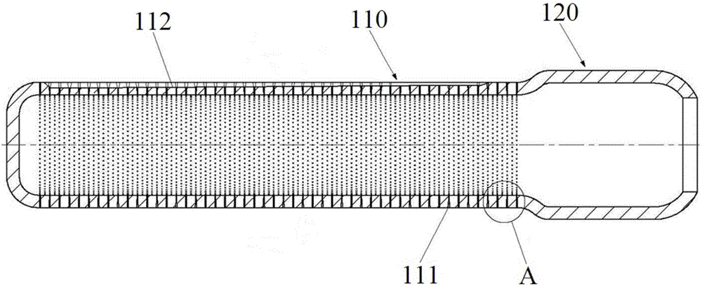
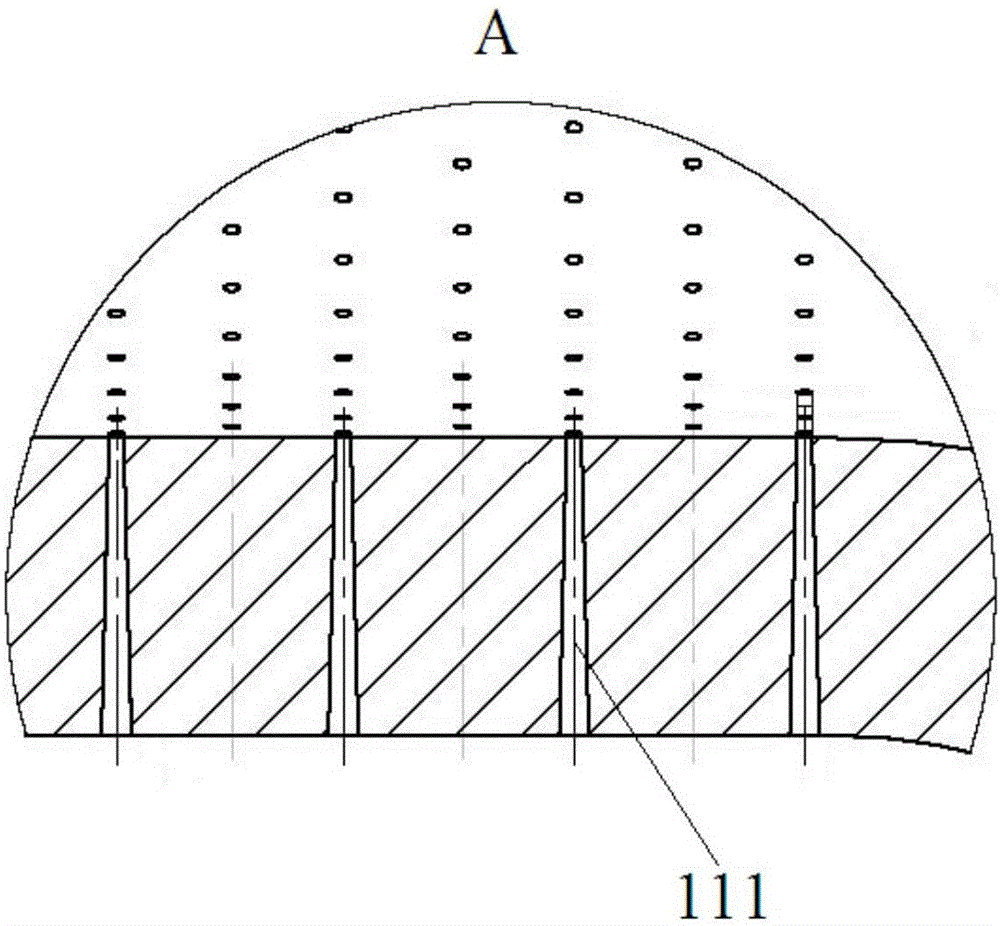
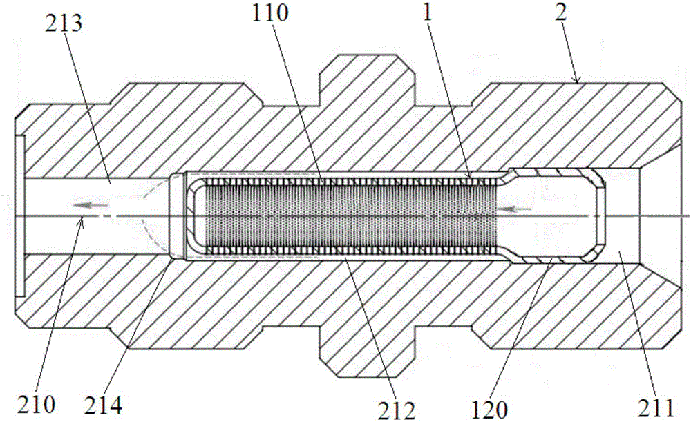
[0031] like figure 1 and figure 2 As shown, a fuel pre-atomizer provided according to an embodiment of the present invention includes a cup-shaped body 1, one end of the cup-shaped body 1 is a blind end, and the other end is an open end, and the cup-shaped body 1 The side wall is provided with an atomizing part 110 and a mounting part 120, the atomizing part 110 is adjacent to the blind end, the mounting part 120 is located at the open end of the cup-shaped body 1, and the atomizing part 110 A plurality of atomization holes 111 are arranged on the side wall of the side wall, and the diameter of the atomization holes 111 is 10-60um.

[0032] In the above embodiments, the fuel oil pre-atomizer is used for pre-atomizing diesel oil, and the atomizing part 110 of the cup-shaped body 1 is provided with a plurality of atomizing holes 111 with diameters ranging from 10 to 60 um, which can The diesel oil passing through the cup-shaped body 1 is pre-atomized when it flows out evenly ...


PUM


Abstract

The invention discloses a fuel oil pre-atomization device, a fuel oil atomization joint and a manufacturing method of the fuel oil pre-atomization device. The fuel oil pre-atomization device comprises a cup-shaped body of which one end is a blind end and the other end is an open end. The side wall of the cup-shaped body is provided with an atomization portion adjacent to the blind end and a mounting portion located at the open end of the cup-shaped body. The side wall of the atomization portion is provided with multiple atomization holes with the pore diameter ranging from 10 micrometers to 60 micrometers. The fuel oil atomization joint comprises a straight-through connecting joint in which a step hole is formed. The fuel oil pre-atomization device is assembled in the step hole. The manufacturing method of the fuel oil pre-atomization device comprises the following steps that the cup-shaped body with the mounting portion and the atomization portion is stamped through a die; the atomization holes are machined in the atomization portion of the cup-shaped body through lasers; diversion trenches are cut in the atomization portion of the cup-shaped body; and polishing treatment is conducted on the cup-shaped body. By the adoption of the fuel oil pre-atomization device, pre-atomization can be conducted on fuel oil, the pre-atomized fuel oil can be prevented from forming an eddy in a spray head, and the injection pressure and the atomization effect of the fuel oil are guaranteed.

Description

technical field [0001] The invention belongs to the field of fuel pretreatment for fuel engines, and in particular relates to a fuel pre-atomizer, a fuel atomization joint and a method for manufacturing the fuel pre-atomizer. Background technique [0002] The fuel injector in the existing high-pressure common rail fuel injection system of the fuel engine is equipped with a slit-type filter element, which can only be used to roughly filter the missing impurities and cannot achieve fine filtration and pre-atomization of the fuel, resulting in the fuel being injected into the nozzle. The fineness and uniformity of the oil beam in the combustion chamber are poor, which is not conducive to the full combustion of the fuel. Contents of the invention [0003] In order to solve the above problems, a fuel pre-atomizer is needed, which can not only meet the fine filtration of fuel, but also realize the pre-atomization of fuel before it is sprayed from the nozzle, and at the same time...

Claims


Application Information

Patent Timeline
Patent Type & Authority Applications(China)
IPC IPC(8): B05B1/10B05B1/26B05B15/00B05B12/00
CPCB05B1/10B05B1/26B05B12/00B05B15/00B05B15/40Y02T10/12
Inventor 康璇田少华康旭光
Owner 陕西华远动力科技有限公司
Learn More