Machine tool clamp

A technology for machine tool fixtures and clamping bodies, which is used in clamping, manufacturing tools, components of boring machines/drilling machines, etc., can solve the problems of not simple application and increase production costs, and achieve simple structure, strong versatility, and reduced production costs. Effect

Inactive Publication Date: 2016-10-12
镇江市宏业科技有限公司
View PDF6 Cites 4 Cited by
  • Summary
  • Abstract
  • Description
  • Claims
  • Application Information

AI Technical Summary

Problems solved by technology

At this stage, the machine tool fixtures for fixing and clamping workpieces are highly targeted, and the application is not simple and common enough, and manual assistance is often required. For some enterprises with many types of workpieces, it is necessary to invest a certain amount of manpower and material resources to manufacture each processing workpiece. The clamping device indirectly increases the production cost

Method used


Image

  • Machine tool clamp

Examples


Embodiment Construction

[0015] The following will clearly and completely describe the technical solutions in the embodiments of the present invention with reference to the drawings in the embodiments of the present invention.

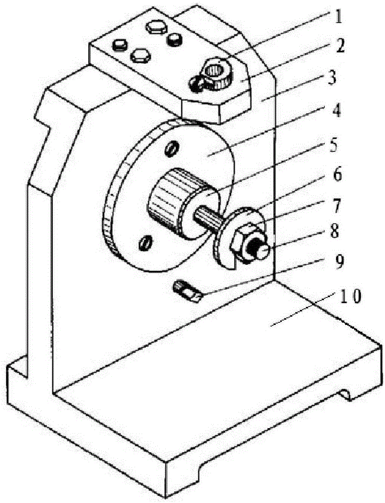
[0016] Such as figure 1 Shown, a kind of machine tool fixture comprises:

[0017] The positioning plate 10 and the clamp body 3 erected on the positioning plate 10;

[0018] The clamping device includes a screw rod 8 and an open washer 6 and a nut 7 passing through the screw rod 8 in turn;

[0019] The guiding device includes a drill template 2 arranged above the clamp body 3 and parallel to the positioning plate 10 and a drill sleeve 1 arranged above the drill template 2 .

[0020] Wherein, a support plate 4 is provided at the center of the surface of the clamp body 3, and a diamond-shaped pin 9 is provided below, and a cylindrical pin 5 is provided on the support plate 4, and one end of the screw rod 8 is inserted into the cylindrical pin 5.

[0021] The function of the c...


PUM


Abstract

The invention discloses a machine tool clamp which comprises a positioning plate, a clamp body, a clamping device and a guide device. The machine tool clamp is simple in structure, is strong in universality, is used for processing a common machine tool, can meet milling processing needs of most of workpieces, and has the advantage of reducing production cost.

Description

technical field [0001] The invention relates to a machine tool fixture. Background technique [0002] When the workpiece is milled on the milling machine, fixtures are needed to fix, guide and clamp the workpiece. At this stage, the machine tool fixtures for fixing and clamping workpieces are highly targeted, and the application is not simple and common enough, and manual assistance is often required. For some enterprises with many types of workpieces, it is necessary to invest a certain amount of manpower and material resources to manufacture each processing workpiece. The clamping device indirectly increases the production cost. Contents of the invention [0003] In order to solve the above technical problems, the present invention provides a machine tool clamp, which has a simple structure and strong versatility, is used for common machine tool processing, can meet the milling processing of most workpieces, and has the advantage of reducing production costs. [0004] ...

Claims


Application Information

Patent Timeline
Patent Type & Authority Applications(China)
IPC IPC(8): B23Q3/06B23B47/28B23B49/02
CPCB23Q3/06B23B47/28B23B49/02
Inventor 朱苏尔
Owner 镇江市宏业科技有限公司
Why Eureka
Try Eureka