
Movable cutting machine achieving positioning through laser lamp

A laser light and mobile technology, applied in the direction of grinding racks, grinding machine parts, grinding/polishing equipment, etc., can solve the problems of cutting machine operation troubles, reduce labor efficiency, limit the processing area, etc., and achieve reduction The risk of sparks splashing, the effect of improving labor efficiency and reducing the handling time

Inactive Publication Date: 2016-10-12
李丽芳
View PDF9 Cites 2 Cited by
  • Summary
  • Abstract
  • Description
  • Claims
  • Application Information

AI Technical Summary

Problems solved by technology

[0002] The popularity of machining is the key to the development of the company. The cutting machines required for processing some materials such as steel are also becoming more and more popular. However, the operation of traditional cutting machines is troublesome. The speed cannot be adjusted, and it cannot be adjusted according to different materials. The cutting disc is very worn out and needs to be replaced frequently, which greatly reduces the labor efficiency. Moreover, due to the heavy body, the cutting machine is also very difficult to move, and the flexibility is poor, which limits the processing area. The protective measures of the traditional cutting machine are also very limited. Only the protective cover above the cutting disc is used for safety protection, which has potential safety hazards.

Method used


Image

  • Movable cutting machine achieving positioning through laser lamp
  • Movable cutting machine achieving positioning through laser lamp

Examples


Embodiment Construction

[0014] The following will clearly and completely describe the technical solutions in the embodiments of the present invention with reference to the accompanying drawings in the embodiments of the present invention. Obviously, the described embodiments are only some, not all, embodiments of the present invention.

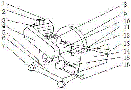
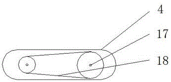
[0015] refer to Figure 1-2 , a mobile cutting machine with laser light positioning, including a motor 1, an emergency switch 3, a support frame 5, a speed control switch 8 and a grinding wheel protective cover 9, the motor 1 is equipped with a heat dissipation window 2, and the left side of the heat dissipation window 2 An emergency switch 3 is installed, a gearbox 4 is installed on the left side of the emergency switch 3, a base 7 is installed under the support frame 5, a fuselage 10 is installed under the speed control switch 8, and a grinding wheel protective cover is installed on the right side of the speed control switch 8 9. A grinding wheel 11 is installed un...


PUM


Abstract

The invention discloses a mobile cutting machine for laser lamp positioning, which comprises a motor, an emergency switch, a support frame, a speed regulating switch and a grinding wheel sheet protective cover. The surface of the motor is equipped with a heat dissipation window, and an emergency Switch, the gearbox is installed on the left side of the emergency switch, the base is installed under the support frame, the fuselage is installed under the speed control switch, and the grinding wheel protective cover is installed on the right side of the speed control switch, the grinding wheel A grinding wheel is installed under the protective cover, and a laser light is installed on the surface of the protective cover of the grinding wheel. The invention uses the speed control switch to process materials of different materials, which greatly reduces the wear of the cutting piece and improves its service life, and uses the laser light for positioning without pre-testing the alignment direction before cutting, directly through the laser The lamp illuminates the point to position the cutting, which reduces the labor intensity, and the base is equipped with pulleys to make use of the movement and placement of the machine, reducing the handling time.

Description

technical field [0001] The invention relates to the technical field of mobile cutting machines, in particular to a mobile cutting machine with laser lamp positioning. Background technique [0002] The popularity of machining is the key to the development of the company. The cutting machines required for processing some materials such as steel are also becoming more and more popular. However, the traditional cutting machines are troublesome to operate. The speed cannot be adjusted, and it cannot be adjusted according to different materials. The cutting blade is very worn out and needs to be replaced frequently, which greatly reduces the labor efficiency. Moreover, due to the heavy body, the cutting machine is also very difficult to move, and the flexibility is poor, which limits the processing area. The protective measures of the traditional cutting machine are also very limited. Only the protective cover above the cutting disc is used for safety protection, which has potenti...

Claims


Application Information

Patent Timeline
IPC IPC(8): B24B27/06B24B55/04B24B41/00B24B41/02
CPCB24B27/06B24B27/0683B24B41/00B24B41/02B24B55/04
Inventor 李丽芳
Owner 李丽芳
Learn More