Light-weight high-speed large-load lower limb exoskeleton robot

An exoskeleton robot, large-load technology, applied in manipulators, program-controlled manipulators, manufacturing tools, etc., can solve the problems of low torque and insufficient compactness, and achieve the effect of increasing compactness, increasing compactness, and improving load capacity.

Active Publication Date: 2016-10-12
HARBIN INST OF TECH
View PDF5 Cites 9 Cited by
  • Summary
  • Abstract
  • Description
  • Claims
  • Application Information

AI Technical Summary

Problems solved by technology

[0003] In order to solve the problem that the existing exoskeleton robot is not compact enough and the torque is low when the rotation reaches the angle when it is driven by a hydraulic cylinder, the present invention proposes a light-weight, high-speed and large-load lower limb exoskeleton robot

Method used


Image

  • Light-weight high-speed large-load lower limb exoskeleton robot
  • Light-weight high-speed large-load lower limb exoskeleton robot
  • Light-weight high-speed large-load lower limb exoskeleton robot

Examples


specific Embodiment approach 1

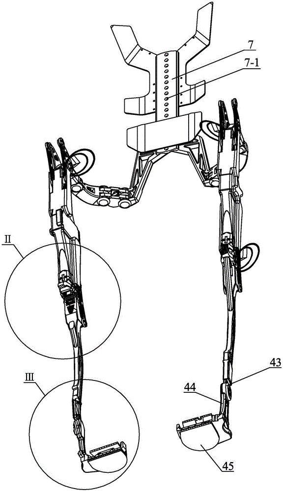
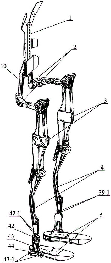
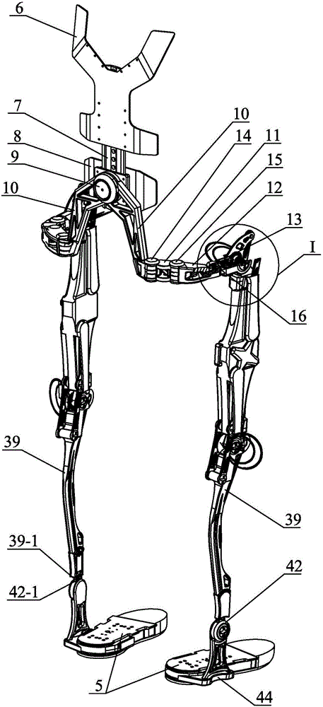
[0026] Specific implementation mode one: combine Figure 1 to Figure 6 Describe this embodiment, this embodiment includes backboard 1, connecting shaft 9, two hip joints 2, two thighs 3, two calves 4 and two foot parts 5;

[0027] Each thigh 3 comprises a hip joint hydraulic drive part and a knee joint hydraulic drive part;

[0028] The hip joint hydraulic driving components include the hip joint output connecting rod 22, the hip joint hydraulic cylinder connecting joint 23, the hip joint hydraulic piston rod 24, the hip joint hydraulic cylinder support cover 25, the hip joint hydraulic cylinder body 26 and the hip joint tension pressure sensor 33, The lower end of the hip joint hydraulic piston rod 24 is set in the hip joint hydraulic cylinder body 26, the upper end of the hip joint hydraulic piston rod 24 is connected with the hip joint tension pressure sensor 33, and the upper end of the hip joint tension pressure sensor 33 is connected with the hip joint hydraulic cylinder...

specific Embodiment approach 2

[0031] Specific implementation mode two: combination figure 1 and image 3 Describe this embodiment, the back panel 1 of this embodiment comprises shoulder binding plate 6, adjustment plate 7 and waist binding plate 8, the upper end of adjustment plate 7 is connected with shoulder binding plate 6 by connecting element, the lower end of adjustment plate 7 It is connected with the waist binding plate 8 by connecting elements. Other components and connections are the same as those in the first embodiment.

specific Embodiment approach 3

[0032] Specific implementation mode three: combination figure 1 To describe this embodiment, the adjusting plate 7 of this embodiment is vertically provided with a plurality of connection holes 7-1. The adjustment of the waist height is realized through the connection holes 7 - 1 at different positions on the adjustment plate 7 and the waist binding plate 8 . Other components and connections are the same as those in the second embodiment.


PUM


Abstract

A light-weight high-speed large-load lower limb exoskeleton robot solves the problems that when driven by hydraulic cylinders, an existing exoskeleton robot is not compact enough and is low in torque when rotating by an angle. Two hip joints are symmetrically arranged on the two sides of a rear back plate. Outer-stretching and inner-bending joint rods on the two hip joints are hinged to a waist binding plate through connecting shafts. The two hip joints, two thighs, two shanks and two foot parts correspond one to one from top to bottom. Bending and stretching joints on the hip joints are connected with hip joint hydraulic cylinder supporting covers on hip joint hydraulic drive parts through connecting elements. The lower ends of hip joint hydraulic cylinders are fixedly connected with the shanks. The upper ends of knee joint hydraulic cylinders are fixedly connected with third inner and outer rotary joint rods on the hip joints. Knee joint hydraulic cylinder supporting covers are connected with knee joint rotary connecting pieces on the shanks through connecting elements. Knee joint shells on the shanks are connected with the foot parts. The robot is used for load-carrying walking and can be used for rescue relief and other occasions where goods and materials need to be transported.

Description

technical field [0001] The invention relates to an exoskeleton robot, in particular to a light-weight, high-speed, large-load lower limb exoskeleton robot. Background technique [0002] At present, the exoskeleton robot has been favored by the majority of researchers for its unique man-machine combination method. There are two driving methods: one is driven by a rotary actuator, and the other is realized by a linear actuator. sports. Among the current existing linear actuators, the hydraulic cylinder occupies the main position. However, the current drive connection methods all choose to be directly connected to the drive, and the hydraulic cylinder is arranged obliquely between the thigh and the calf, see Figure 9 In this way, during the movement, the hydraulic cylinder will move with the actuator, which will first affect the overall compactness, and the peak value of the torque curve formed by it cannot be set at a larger angle, which will cause the exoskeleton to climb ...

Claims


Application Information

Patent Timeline
Patent Type & Authority Applications(China)
IPC IPC(8): B25J9/00
CPCB25J9/0006B25J9/0009
Inventor 朱延河张国安
Owner HARBIN INST OF TECH
Why Eureka
Try Eureka