Slicer, feeding device thereof and slicing production line

A slicer and driving device technology, applied in the manufacture of thin wood chips, wood processing equipment, manufacturing tools, etc., can solve the problems of different lengths of materials, low production efficiency, complex structure, etc., to reduce the possibility of injury, reduce the Artificial input, the effect of ensuring personal safety

Active Publication Date: 2016-10-12
邹平县永诚机械有限公司
View PDF7 Cites 0 Cited by
  • Summary
  • Abstract
  • Description
  • Claims
  • Application Information

AI Technical Summary

Problems solved by technology

Due to the limitation of the width of the conveyor and the way of feeding, putting the material on the conveyor belt can only be done manually or with mechanical assistance. Therefore, multiple people are required to feed the material continuously at the same time to meet the production needs of subsequent equipment, and the labor force is very large.
[0003] In addition, the feeding system of the traditional wood chipper is not only complicated in structure, but also its feeding belt, motor reducer, feeding roller, etc. are all vulnerable parts, which not only easily cause discontinuous slice production, but also make the maintenance of the slicer difficult. Difficulty and high cost
[0004] Moreover, since the materials that need to be sliced ​​or broken are often mixed with foreign objects (such as stones, iron and other hard objects), if these foreign objects enter the slicer with the

Method used


Image

  • Slicer, feeding device thereof and slicing production line
  • Slicer, feeding device thereof and slicing production line
  • Slicer, feeding device thereof and slicing production line

Examples


Embodiment Construction

[0083] In order to better explain the present invention and facilitate understanding, the present invention will be described in detail below through specific embodiments in conjunction with the accompanying drawings.

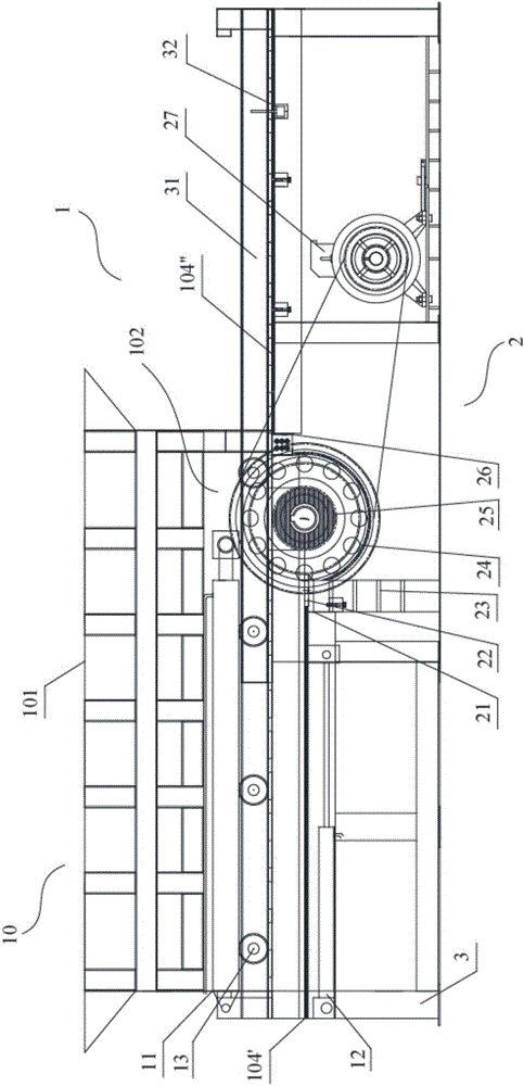
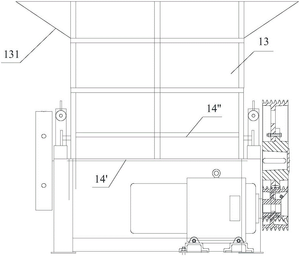
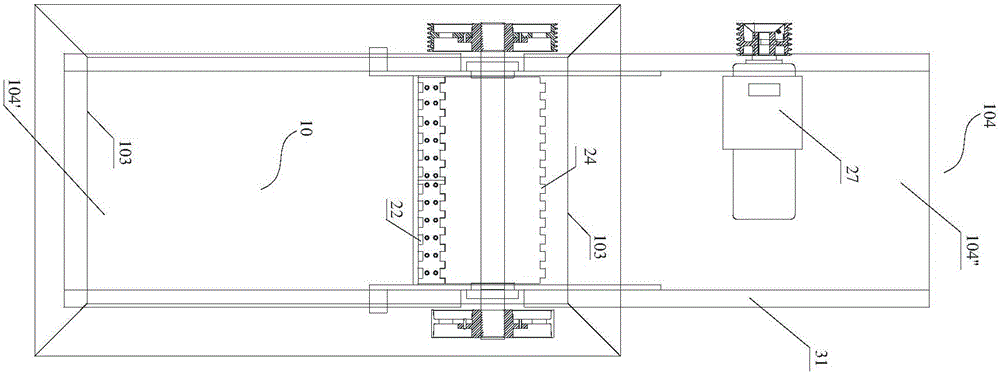
[0084] see figure 1 , figure 2 and image 3 , the slicer according to the first embodiment of the present invention, which includes: a frame 3 and a feeding mechanism 1 and a cutting mechanism 2 arranged on the frame 3 .

[0085] Wherein, the feeding mechanism 1 includes a moving bin 103 , a bottom plate 104 and a first driving device 11 . The base plate 104 and the mobile feed bin 103 encircle the material placement space, the base plate 104 is fixed on the frame 3, the material outlet 102 of the feed storage space is opened on the base plate 104, the material inlet 101 of the feed storage space is located at the mobile feed bin 103, and the mobile feed bin 103 is movably arranged on the bottom plate 104, and when moving on the bottom plate 104, the moving...


PUM


Abstract

The present invention relates to a slicer, a feeding device thereof and a slicing production line. The slicer comprises a rack, and a feeding mechanism and a cutting mechanism which are disposed on the rack. The feeding mechanism comprises a movable bin (103), a bottom plate (104) and a first drive device (11). The bottom plate (104) and the movable bin (103) form a material placing space, the bottom plate (104) is fixed on the rack (3), a material exit (102) of the material placing space is formed in the bottom plate (104) while a material entrance (101) of the material placing space is formed in the movable bin (103), the movable bin (103) is movably disposed on the bottom plate (104), and when moving on the bottom plate (104), the movable bin (103) pushes materials on the bottom plate (104) to move towards the material exit (102) formed in the bottom plate (104) and to reach the cutting mechanism through the material exit (102). The first drive device (11) provides power for the movable bin (103) to move on the bottom plate (104). Through split arrangement of the movable bin and the bottom plate, the slicer is simple in structure, convenient to feed and high in efficiency, quick-wear parts are reduced, manpower is saved, and personnel security is raised.

Description

technical field [0001] The invention relates to a slicer, a feeding device therein and a slice production line based on the slicer, which are used for slicing and crushing wood and various wood materials. Background technique [0002] The feeding system of the traditional wood chipper is driven by the motor reducer, and the wood is sent to the cutting part through the conveyor belt for slicing and crushing. Due to the limitation of the width of the conveyor and the way of feeding, putting the material on the conveyor belt can only be done manually or with mechanical assistance. Therefore, multiple people are required to feed the material continuously at the same time to meet the production needs of subsequent equipment, and the labor force is very large. . [0003] In addition, the feeding system of the traditional wood chipper is not only complicated in structure, but also its feeding belt, motor reducer, feeding roller, etc. are all vulnerable parts, which not only easily...

Claims


Application Information

Patent Timeline
IPC IPC(8): B27L5/06B27L11/00
CPCB27L5/06B27L11/00B27L11/002
Inventor 傅强
Owner 邹平县永诚机械有限公司
Why Eureka
Try Eureka