
Skidder cable rack assembly

A skidder and assembly technology, applied in the direction of the clockwork mechanism, hoisting device, etc., can solve the problems of lack of structural assembly, complicated wire rope support structure, etc., achieve simple structure, ensure work efficiency and reliability, reduce The effect of cost of use

Inactive Publication Date: 2016-10-12
XCMG CONSTR MACHINERY
View PDF7 Cites 0 Cited by
  • Summary
  • Abstract
  • Description
  • Claims
  • Application Information

AI Technical Summary

Problems solved by technology

For the skidder cable frame, it is necessary to ensure the unwinding and receiving action of the steel wire rope, and to reasonably limit the movement space of the steel wire rope in each direction. The requirements for the support structure of the steel wire rope are relatively complicated. At present, there is a lack of such a structural assembly

Method used


Image

  • Skidder cable rack assembly
  • Skidder cable rack assembly
  • Skidder cable rack assembly

Examples


Embodiment Construction

[0026] The present invention will be further described below in conjunction with accompanying drawing.

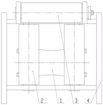
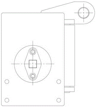
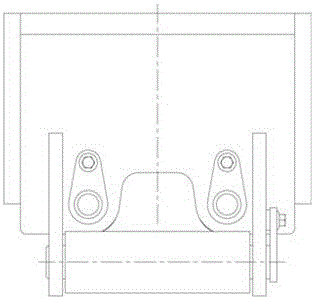
[0027] Such as figure 1 , figure 2 and image 3 As shown, a cable frame assembly of a skidder according to the present invention includes a first guide shaft assembly 1 that supports the wire rope and assists in limiting the movement space of the wire rope, a second guide shaft assembly 2 and a third guide shaft assembly that assists in limiting the movement space of the wire rope Shaft assembly 3, and the cable frame 4 that installs each assembly; There are two second guide shaft assemblies 2, all perpendicular to the first guide shaft assembly 1, located at the front of the first guide shaft assembly 1; Three guide shaft assemblies 3 are located at the front of the first guide shaft assembly 1, parallel and higher than the first guide shaft assembly 1; The space defined by the assembly 3 passes through and presses on the first guide shaft assembly 1 to move.

[0028]...


PUM


Abstract

The invention discloses a skidder cable rack assembly which comprises a first guide shaft assembly for supporting a steel wire rope and assisting to limit a steel wire rope motion space, second guide shaft assemblies and a third guide shaft assembly for assisting to limit the steel wire rope motion space and a cable rack for installing the assemblies. The number of the second guide shaft assemblies is two, and the second guide shaft assemblies are both perpendicular to the first guide shaft assembly and are located at the front portion of the first guide shaft assembly. The third guide shaft assembly is located at the front portion of the first guide shaft assembly and is parallel to and higher than the first guide shaft assembly. When steel wire rope take-up or pay-off operation is performed, the steel wire rope penetrates through the space defined by the second guide shaft assemblies and the third guide shaft assembly and presses the first guide shaft assembly to move. By the adoption of the arrangement structure of the three assemblies, the steel wire rope can efficiently work in a reasonable space range, and accordingly the phenomenon that two large steel wire rope sliding amplitude causes rope clamping and the working reliability of a whole machine is prevented.

Description

technical field [0001] The invention relates to a skidder, in particular to a cable frame assembly of a skidder, which belongs to the field of forestry machinery. Background technique [0002] The skidder is a kind of tractor, which is mainly used to pull and drag the logs in the forest to the destination. Due to the large diameter, long size and heavy weight of the log, the skidder needs to use the hook at the end of the wire rope to bind the log when it is working, and then pull it. The steel wire rope needs to be supported by the cable frame, which is equivalent to a pulley in function, and the steel wire rope passes through the cable frame to lift and pull the log. When the wire rope hangs the log, the skidder needs to release the rope, and when the log is hung, it needs to take the rope. No matter whether the rope is received or released, the steel wire rope is all pressed on the cable rack. [0003] When the wire rope is retracted, it will be loaded rapidly, and the...

Claims


Application Information

Patent Timeline
IPC IPC(8): B66D1/74
CPCB66D1/7405B66D2700/01
Inventor 张永胜郭军胜沈勇王小虎韩标崔玉艳钟俊伟安时祥李凯章珍张爱霞
Owner XCMG CONSTR MACHINERY
Learn More