Air precooling compression aircraft engine and hypersonic velocity aircraft

An aero-engine and air pre-cooling technology, which is applied in the cooling of engine components, machines/engines, and engines, can solve problems such as malfunction, low engine specific impulse performance, and large hydrogen consumption, and reduce structural heat load , Improving compression efficiency and increasing fuel specific impulse

Active Publication Date: 2016-10-12
NAT UNIV OF DEFENSE TECH
View PDF6 Cites 36 Cited by
  • Summary
  • Abstract
  • Description
  • Claims
  • Application Information

AI Technical Summary

Problems solved by technology

There are two main deficiencies in this traditional turbofan engine: one is that it cannot work normally when flying at hypersonic speed (usually greater than 5 times the speed of sound)
The second is that due to the limitation of the temperature resistance of the turbine blade material, the combustion temperature cannot be too high even when flying at a low speed (currently the highest cannot exceed 1700°C), which is far from the theoretical combustion temperature of air and kerosene, and the work potential of the gas is not fully utilized. , resulting in poor engine thrust performance
From the perspective of the working process of the engine, the advantage of this solution is that it can expand the speed adaptation range of traditional aero-engines; the disadvantage is that it requires additional coolant, and the coolant is continuously consumed during the working process of the engine and cannot be recycled
[0010] Through the analysis and comparison of several foreign air pre-cooling aero-engine schemes, it can be seen that either additional coolant is used to cool the air, and the engine needs to consume coolant continuously during operation, which is obviously not practical; or liquid hydrogen fuel is used as the coolant, but cooling is required. In the air and combustion chamber, the hydrogen consumption is larger than the flow required for normal combustion, resulting in low specific impulse performance of the engine and poor economy

Method used


Image

  • Air precooling compression aircraft engine and hypersonic velocity aircraft
  • Air precooling compression aircraft engine and hypersonic velocity aircraft
  • Air precooling compression aircraft engine and hypersonic velocity aircraft

Examples


Embodiment Construction

[0040] It should be noted that, in the case of no conflict, the embodiments in the present application and the features in the embodiments can be combined with each other. The present invention will be described in detail below with reference to the accompanying drawings and examples.

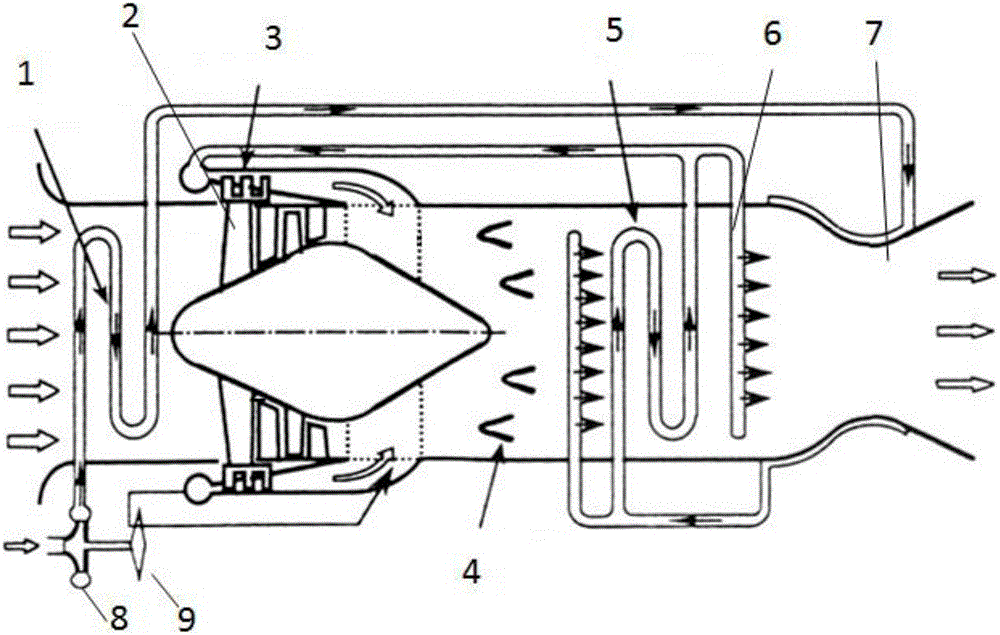
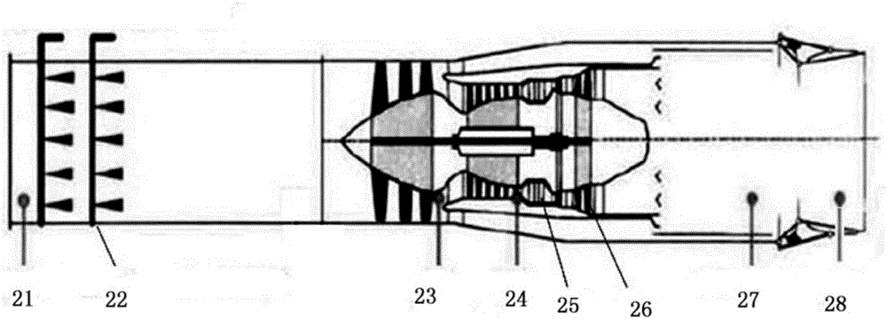
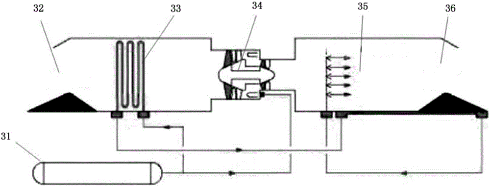
[0041] refer to Figure 4 , the preferred embodiment of the present invention provides a kind of air pre-cooling compression aero-engine, comprises the intake passage 41 that is arranged in sequence, compressor 42, combustion chamber 43 and nozzle 44, and compressor 42 is provided with and provides driving force for it Turbine 45; the air precooling compression aeroengine of this embodiment also includes: a first heat exchanger 46, located between the intake passage 41 and the compressor 42, for using the coolant to compress the air after the intake passage 41 Cooling; the coolant pump 47 has a coolant outlet communicated with the first heat exchanger 46 and a coolant recovery port communicate...


PUM


Abstract

The invention discloses an air precooling compression aircraft engine and a hypersonic velocity aircraft. The air precooling compression aircraft engine comprises an intake way, an air compressor, a combustion chamber and a spraying pipe arranged in sequence; and the air compressor is provided with a turbine for providing driving force. The air precooling compression aircraft engine further comprises a first heat exchanger for adopting a circular cooling agent to cool air introduced by the intake way, a cooling agent pump provided with a cooling agent outlet communicated with the first heat exchanger and a cooling agent recovery port communicated with a second heat exchanger for recovering the cooling agent, the second heat exchanger for using liquid hydrogen output by a liquid hydrogen pump as a cold source to cool the heated cooling agent and leading out the cooled cooling agent to the cooling agent pump for recycling, the liquid hydrogen pump connected with an inlet of the second heat exchanger for supplying liquid hydrogen as a fuel, and an injector positioned between the air compressor and the combustion chamber and communicated with the second heat exchanger for injecting air compressed by the air compressor and hydrogen exchanged heat by the second heat exchanger into the combustion chamber.

Description

technical field [0001] The invention relates to the field of aeroengines, in particular to an air precooling compression aeroengine. In addition, the present invention also relates to a hypersonic aircraft comprising the above-mentioned air-precooled compression aeroengine. Background technique [0002] At present, there are three main types of engines used in the aviation field: piston internal combustion engines, turbofan / turbojet engines, and turboshaft / turboprop engines. [0003] In 1903, the Wright Brothers of the United States used a 4-cylinder water-cooled gasoline internal combustion engine to manufacture the world's first manned aircraft, creating a new era in which the piston internal combustion engine became the aircraft power plant. However, because the high-power piston internal combustion engine is very heavy and can only be propelled by propellers, it cannot make the aircraft fly at supersonic speed. [0004] In April 1937, the British Whittle developed the ...

Claims


Application Information

Patent Timeline
Patent Type & Authority Applications(China)
IPC IPC(8): F02C3/20F02C7/143F02C7/16
CPCF02C3/20F02C7/143F02C7/16
Inventor 刘卫东刘世杰蒋露欣任春雷张韬岳晓菲李西鹏
Owner NAT UNIV OF DEFENSE TECH
Why Eureka
Try Eureka