LNG vaporizer utilizing phase-change heat transfer technology and vaporization method

A phase change heat and vaporizer technology, applied in indirect heat exchangers, lighting and heating equipment, etc., can solve problems such as deterioration and achieve the effect of simple structure

Inactive Publication Date: 2016-10-12
JIANGSU UNIV OF SCI & TECH
View PDF7 Cites 8 Cited by
  • Summary
  • Abstract
  • Description
  • Claims
  • Application Information

AI Technical Summary

Problems solved by technology

When the high-temperature second heat exchange medium flows through the heat exchange pipe of the second heat exchange medium, it exchanges heat with the first heat exchange medium, so that the first heat exchange medium vaporizes, changes from a liquid state to a gaseous state, and moves to the vaporizer under the action of buoyancy force The upper part of the shell exchanges heat with the LNG in the LNG heat exchange pipe. After the vaporized first heat exchange medium absorbs the large amount of cold released by the LNG from liquid to gas, it condenses into liquid on the outer wall of the LNG heat exchange pipe. Under the action of gravity, it flows back to the lower part of the carburetor shell for a new vaporization and condensation process, and then realizes the vaporization of LNG; by using the vaporization and condensation process of the first heat transfer medium, the freezing of the heat transfer medium caused by the low temperature of LNG is solved The problem that causes the vaporization performance of the carburetor to deteriorate, and the structure is simpler

Method used


Image

  • LNG vaporizer utilizing phase-change heat transfer technology and vaporization method
  • LNG vaporizer utilizing phase-change heat transfer technology and vaporization method
  • LNG vaporizer utilizing phase-change heat transfer technology and vaporization method

Examples


Embodiment Construction

[0023] Below in conjunction with accompanying drawing and specific embodiment, the present invention will be described in further detail, but the scope of protection of the present invention is not limited to the following examples, all technical schemes obtained by adopting equivalent replacement or equivalent transformation forms are all within the scope of protection of the present invention .

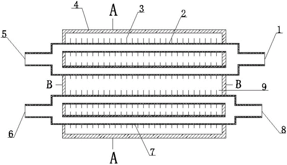
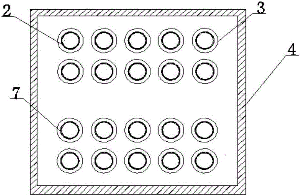
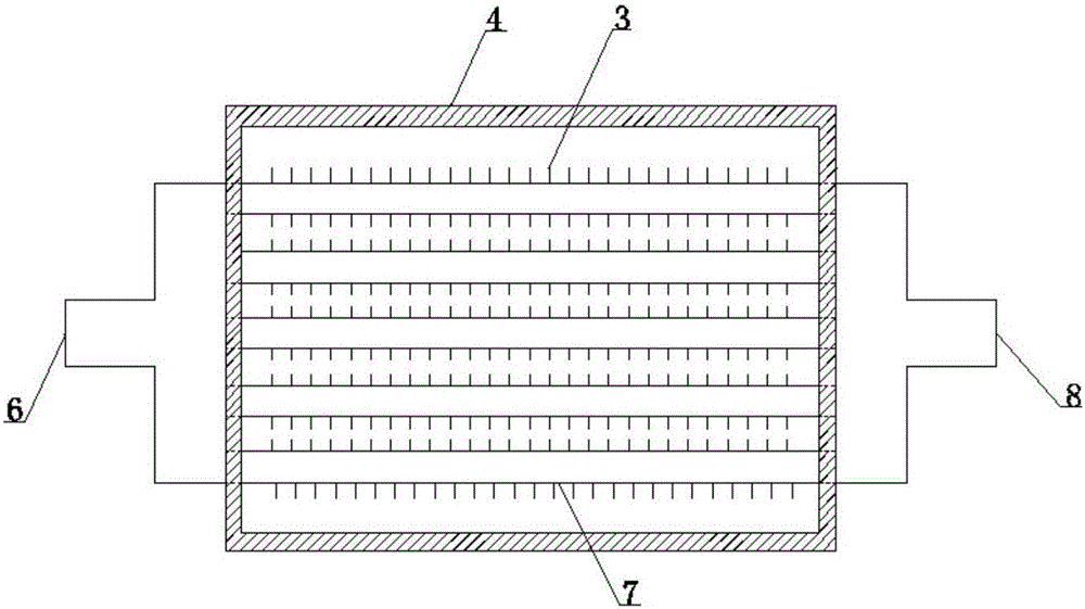
[0024] as attached Figure 1 to Figure 3 As shown, it is an LNG vaporizer using phase-change heat technology according to an embodiment of the present invention, which includes a shell 4 with a first heat exchange medium heat exchange chamber 9, and on the corresponding two side walls of the shell 4, On the upper side wall which is less than half the height of the first heat exchange medium heat exchange chamber 9 and on the lower side wall which is less than half the height of the first heat exchange medium heat exchange chamber 9 are respectively provided with two rows of , with ...


PUM


Abstract

The invention discloses an LNG vaporizer and a vaporization method using phase-change heat technology. The vaporizer includes a shell with a heat exchange chamber for a first heat exchange medium. On the upper side wall of the first heat exchange medium heat exchange chamber with a height of half and on the lower side wall with a height less than half of the first heat exchange medium heat exchange chamber are respectively provided with at least one row of corresponding Through holes, one end of the upper through hole is connected to the LNG heat exchange pipe connected to the LNG inlet and the other end is connected to the LNG outlet, and the lower through hole is connected to one end connected to the second heat exchange medium inlet, and the other end is connected to the second heat exchange medium inlet. The second heat exchange medium heat exchange pipe of the second heat exchange medium outlet, wherein the outer walls of the LNG heat exchange pipe and the second heat exchange medium heat exchange pipe are respectively fitted with several vertical fins along the axial direction. The invention solves the problem that the vaporization performance of the vaporizer deteriorates due to the freezing of the heat exchange medium due to the low temperature of the LNG, and has a simple structure.

Description

technical field [0001] The invention relates to a vaporizer, in particular to an LNG vaporizer and a vaporization method utilizing phase-change heat technology, and belongs to the technical field of heat exchangers. Background technique [0002] With the rapid development of the global economy, the shortage of global oil resources and the increasingly serious environmental pollution problems have led to a sharp increase in the consumption of natural gas with good combustibility and low pollution. Natural gas is gaseous at room temperature, which is not convenient for storage and long-distance transportation. It is transformed into liquefied natural gas (LNG) at -163°C for storage and long-distance transportation. However, before using LNG, it is necessary to use a vaporization device to increase the temperature of LNG at -163°C to natural gas (NG) at about 5°C. [0003] At present, the vaporizers used for LNG vaporization mainly include the following types: [0004] (1) Op...

Claims


Application Information

Patent Timeline
Patent Type & Authority Applications(China)
IPC IPC(8): F28D15/02
CPCF28D15/025
Inventor 赵忠超蒋朋朋沈仁东赵凯陈育平周根明顾晓波
Owner JIANGSU UNIV OF SCI & TECH
Why Eureka
Try Eureka