Static loading experiment device for turret of numerically controlled lathe

A technology of turret turret and static loading, applied in the direction of digital control, measuring device, electrical program control, etc., can solve the problems of many mechanical failure points, complex structure, and failure to consider the influence of turret deformation, etc., and achieve the measurement results Intuitive, low mechanical failure rate effect

Active Publication Date: 2016-10-12
宝鸡忠诚机床股份有限公司
View PDF5 Cites 4 Cited by
  • Summary
  • Abstract
  • Description
  • Claims
  • Application Information

AI Technical Summary

Problems solved by technology

[0003] Domestic loading test devices for turret tool holders are basically experimental platforms based on the performance of the single tool holder, which have the following deficiencies: 1. The tool holder is not considered to be affected by the structure of the lathe and the spindle, wire, etc. after the tool holder is installed on the lathe. Influence of bars, guide rails and other components on tool holder deformation after static force
2. The loading test device is hydraulically controlled and has a complex structure, resulting in many mechanical failure points

Method used


Image

  • Static loading experiment device for turret of numerically controlled lathe
  • Static loading experiment device for turret of numerically controlled lathe
  • Static loading experiment device for turret of numerically controlled lathe

Examples


Embodiment 1

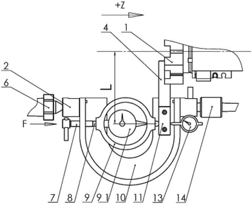
[0024] Embodiment 1 (with reference to figure 2 ) The turret tool rest is loaded in the +Z direction and the deformation of the tool rest is measured, wherein the ejector rod 7 is installed at the left end of the bow frame 10, the turret tool rest 1 is installed on the upper side of the right end of the bow frame 10, and the ejector rod 7 makes the turret The tool post 1 moves in the +Z direction, so that the tool bar 4 moves to the side of the bow frame 10. After the turret tool post 1 moves to a position suitable for placing the force measuring ring 9, place the force-bearing ends of the force measuring ring 9 Insert the steel ball 8, and put it between the cutter bar 4 and the bow frame 10, rotate the ejector rod 7, so that the cutter bar 4 and the ejector rod 7 press against the steel balls 8 at both ends of the force measuring ring 9, and place them on the tool holder 1 The force point of the cutter head is the same as the radius (L) and the dial gauge 13 is fixed in the...

Embodiment 2

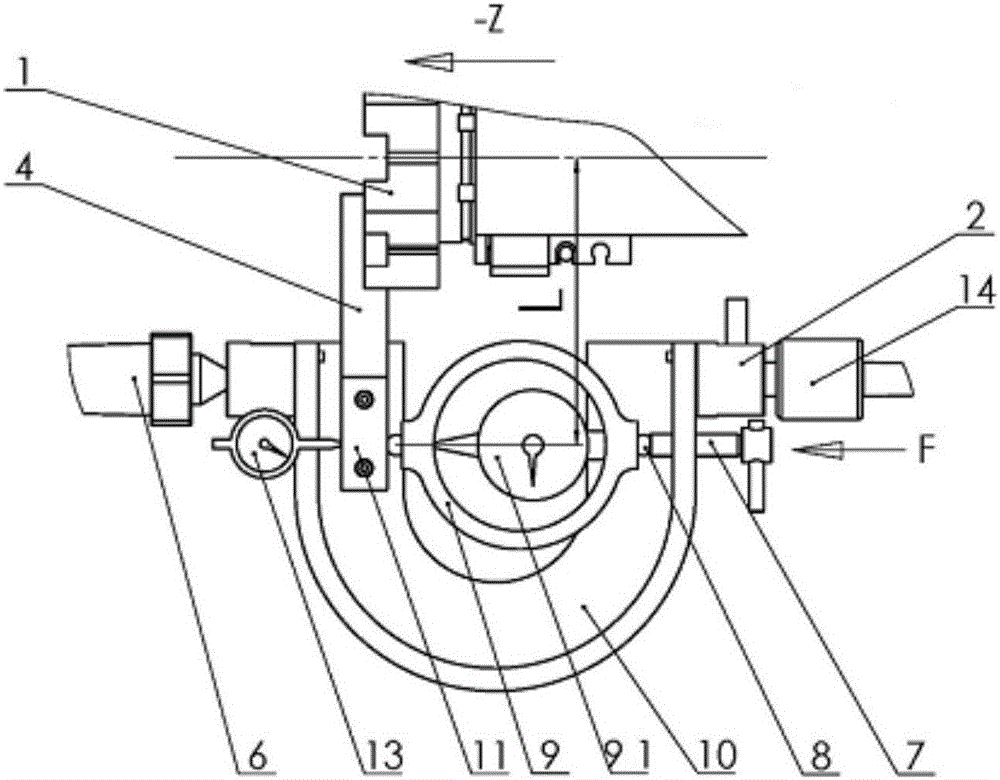
[0025] Embodiment 2 (with reference to image 3 ) The turret tool rest is loaded in the -Z direction and the deformation of the tool rest is measured, wherein the ejector rod 7 is installed at the right end of the bow frame 10, the turret tool rest 1 is installed on the upper side of the left end of the bow frame 10, and the ejector rod 7 makes the turret The tool rest 1 moves in the -Z direction, so that the tool bar 4 moves to the side of the bow frame 10, and after the turret tool rest 1 moves to a position suitable for being placed in the force measuring ring 9, place the force-bearing ends of the force measuring ring 9 Insert the steel ball 8, and put it between the cutter bar 4 and the bow frame 10, rotate the ejector rod 7, so that the cutter bar 4 and the ejector rod 7 press against the steel balls 8 at both ends of the force measuring ring 9, and place them on the tool holder 1 The force point of the cutter head is fixed in the opposite direction of the radius (L), an...

Embodiment 3

[0026] Embodiment 3 (with reference to Figure 4 ) load the turret tool rest 1 in the -Y direction, rotate the bow frame 10 to the place where the bottom surface is perpendicular to the installation surface of the turret tool rest 1, and adjust the measuring direction of the force measuring ring 10 to the Y direction, and the -Y direction The method of measuring the loading of the turret tool post 1 and the deformation of the turret tool post 1 is the same as the implementation principle of the above-mentioned Z direction.

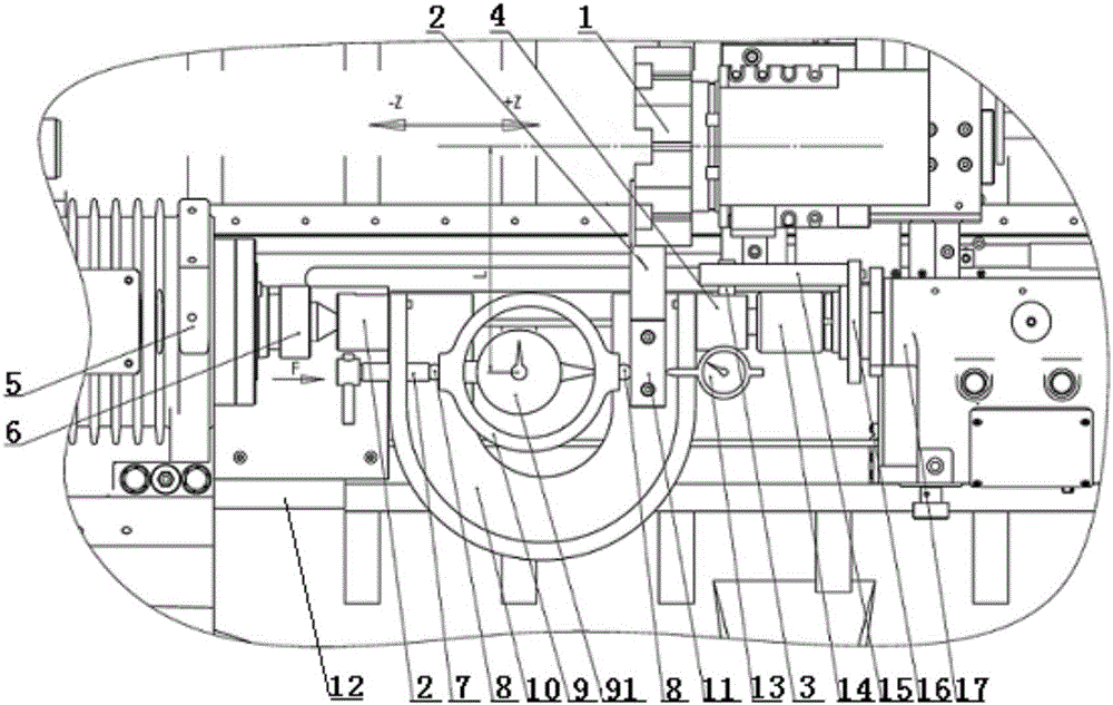
[0027] The function of this experimental device is to assemble the turret tool post on the CNC lathe, to carry out a certain amount of static loading on the tool post in three directions, and to detect the deformation of the tool post. By simulating the working state of the turret tool post during turning, it can The static load deformation of the CNC turret tool post is detected, so as to make a comprehensive evaluation of the performance of the tool post...


PUM


Abstract

The invention discloses a static loading experiment device for a turret of a numerically controlled lathe. The static loading experiment device comprises the turret, a spindle box, a spindle centre, an arch-shape frame, a tailstock centre and a tailstock. The arch-shaped frame is arranged between the spindle box and the tailstock, the turret is arranged on one side of the upper end of the arch-shaped frame, the spindle centre penetrates through a spindle hole of the spindle box, the tailstock centre is inserted in a tailstock sleeve, the opposite ends of the spindle centre and the tailstock centre are inserted into arch-shaped frame connecting sleeves connected to the two ends of the arch-shaped frame through screws, a tool bar is installed at the lower end of the turret, a measuring block extending into the arch-shaped frame is fixedly connected to the lower end of the tool bar, an ejector rod is arranged on one side of the arch-shaped frame in a penetrating mode, a force measuring ring is movably clamped in the arch-shaped frame through the opposite ends of the ejector rod and the measuring block, and a force measuring ring detection meter is arranged in the force measuring ring. According to the device, a certain amount of static loading is carried out on the turret in three directions, the deformation of the turret is detected, and the actual condition installation state and the working stress condition of the turret are simulated; besides, the device is simple in structure, convenient to operate, capable of providing a visible measuring result and low in mechanical failure rate.

Description

technical field [0001] The invention belongs to the technical field of a loading experiment device for a CNC machine tool holder, and in particular relates to a static loading experiment device for a CNC lathe turret tool holder. Background technique [0002] With the development of CNC equipment manufacturing industry, the production and application of high-precision, high-speed and efficient CNC machine tools has become the mainstream trend of domestic machine tool production and machining. However, a considerable part of the prototypes of medium and high-end CNC machine tools in China are imported from abroad, lacking basic research and experimental data analysis, and there is indeed a certain gap with imported machine tools in terms of processing accuracy, reliability, and processing efficiency. As a new type of CNC machine tool The loading experiment device of the key functional component tool holder provides the basis for the loading experiment analysis of the CNC turr...

Claims


Application Information

Patent Timeline
Patent Type & Authority Applications(China)
IPC IPC(8): G01N3/08G01M13/00G01B5/30G05B19/18
CPCG01B5/30G01M13/00G01N3/08G01N2203/0003G01N2203/0016G01N2203/0075G05B19/18
Inventor 王建军孔亚军苏忠堂李文祥
Owner 宝鸡忠诚机床股份有限公司
Why Eureka
Try Eureka