Static Loading Experimental Device for Turret Turret of CNC Lathe
A turret tool holder, static loading technology, applied in the direction of measuring device, digital control, electrical program control, etc., can solve the problems of many mechanical failure points, complex structure, not considering the influence of tool holder deformation, etc., to achieve the measurement results. Intuitive results with low mechanical failure rate
- Summary
- Abstract
- Description
- Claims
- Application Information
AI Technical Summary
Problems solved by technology
Method used
Image
Examples
Embodiment 1
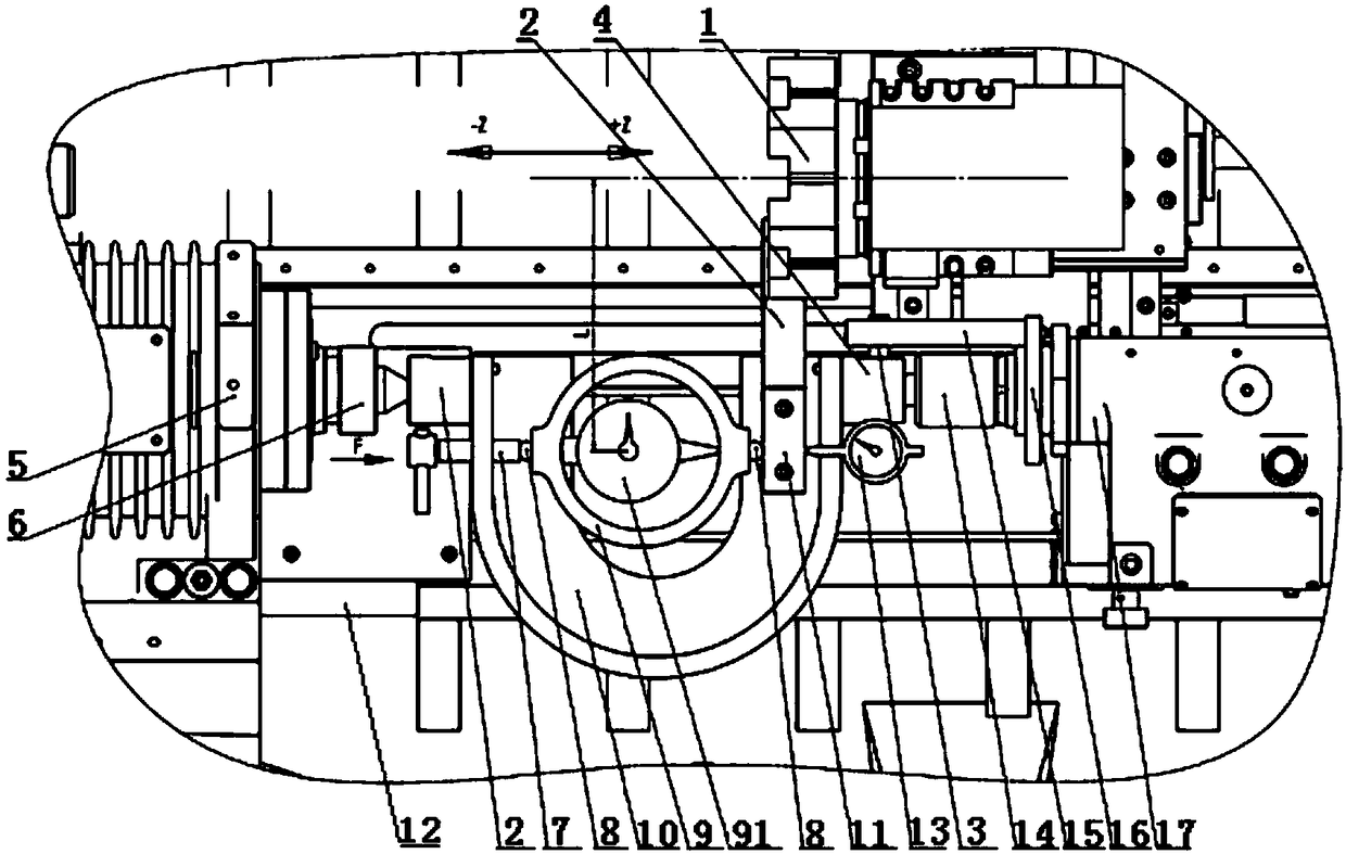
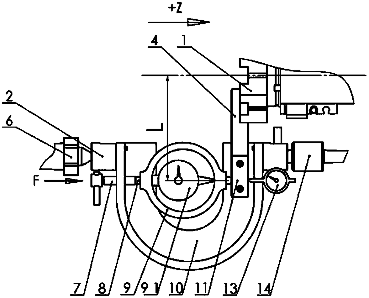
[0024] Embodiment 1 (with reference to figure 2 ) The turret tool rest is loaded in the +Z direction and the deformation of the tool rest is measured, wherein the ejector rod 7 is installed at the left end of the bow frame 10, the turret tool rest 1 is installed on the upper side of the right end of the bow frame 10, and the ejector rod 7 makes the turret The tool post 1 moves in the +Z direction, so that the tool bar 4 moves to the side of the bow frame 10. After the turret tool post 1 moves to a position suitable for placing the force measuring ring 9, place the force-bearing ends of the force measuring ring 9 Insert the steel ball 8, and put it between the cutter bar 4 and the bow frame 10, rotate the ejector rod 7, so that the cutter bar 4 and the ejector rod 7 press against the steel balls 8 at both ends of the force measuring ring 9, and place them on the tool holder 1 The force point of the cutter head is the same as the radius (L) and the dial gauge 13 is fixed in the...
Embodiment 2
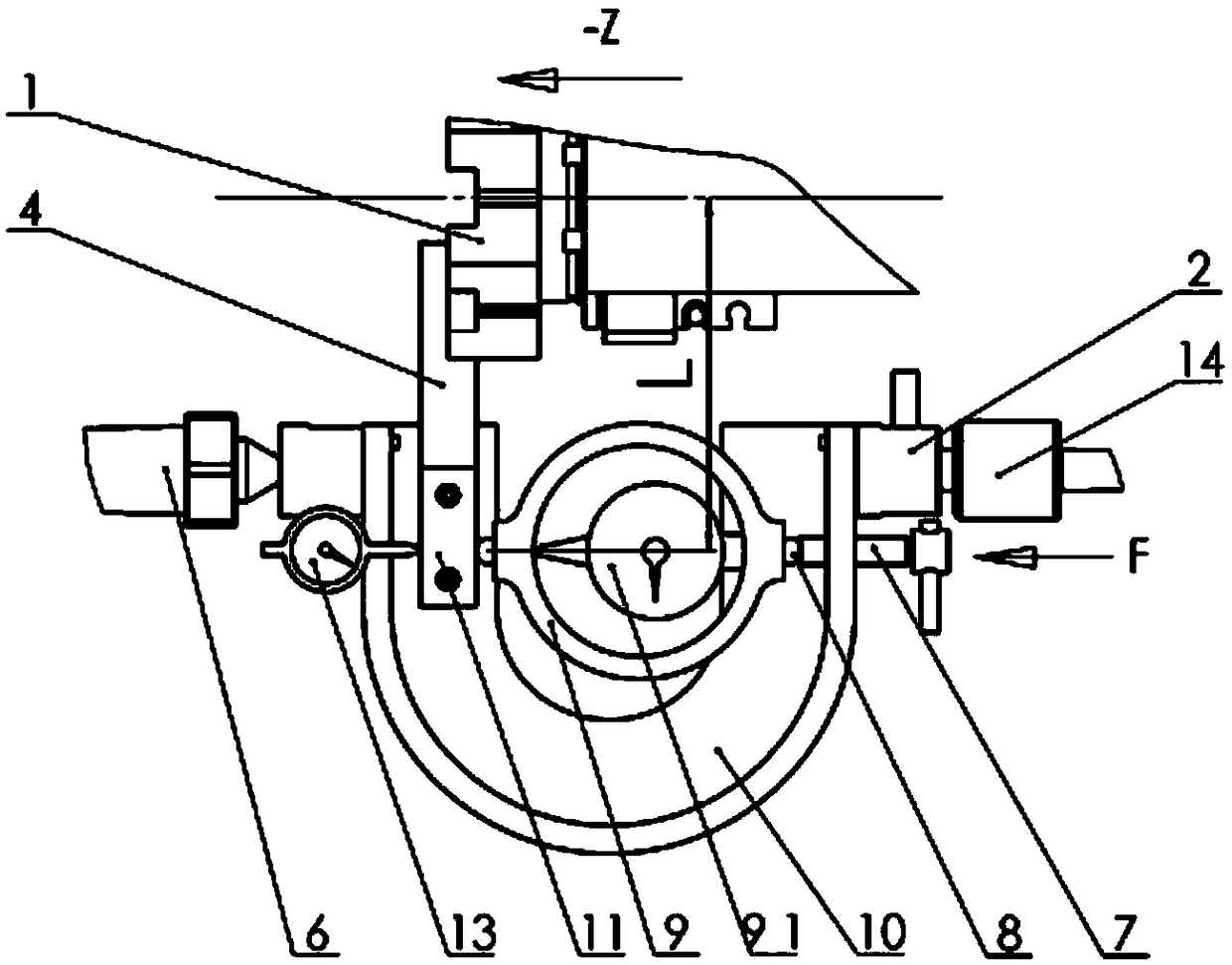
[0025] Embodiment 2 (with reference to image 3 ) The turret tool rest is loaded in the -Z direction and the deformation of the tool rest is measured, wherein the ejector rod 7 is installed at the right end of the bow frame 10, the turret tool rest 1 is installed on the upper side of the left end of the bow frame 10, and the ejector rod 7 makes the turret The tool rest 1 moves in the -Z direction, so that the tool bar 4 moves to the side of the bow frame 10, and after the turret tool rest 1 moves to a position suitable for being placed in the force measuring ring 9, place the force-bearing ends of the force measuring ring 9 Insert the steel ball 8, and put it between the cutter bar 4 and the bow frame 10, rotate the ejector rod 7, so that the cutter bar 4 and the ejector rod 7 press against the steel balls 8 at both ends of the force measuring ring 9, and place them on the tool holder 1 The force point of the cutter head is fixed in the opposite direction of the radius (L), an...
Embodiment 3
[0026] Embodiment 3 (with reference to Figure 4 ) load the turret tool rest 1 in the -Y direction, rotate the bow frame 10 to the place where the bottom surface is perpendicular to the installation surface of the turret tool rest 1, and adjust the measuring direction of the force measuring ring 10 to the Y direction, and the -Y direction The method of measuring the loading of the turret tool post 1 and the deformation of the turret tool post 1 is the same as the implementation principle of the above-mentioned Z direction.
[0027] The function of this experimental device is to assemble the turret tool post on the CNC lathe, to carry out a certain amount of static loading on the tool post in three directions, and to detect the deformation of the tool post. By simulating the working state of the turret tool post during turning, it can The static load deformation of the CNC turret tool post is detected, so as to make a comprehensive evaluation of the performance of the tool post...
PUM
 Abstract
Description
Claims
Application Information
 - R&D
- Intellectual Property
- Life Sciences
- Materials
- Tech Scout
- Unparalleled Data Quality
- Higher Quality Content
- 60% Fewer Hallucinations
Browse by: Latest US Patents, China's latest patents, Technical Efficacy Thesaurus, Application Domain, Technology Topic, Popular Technical Reports.
© 2025 PatSnap. All rights reserved.Legal|Privacy policy|Modern Slavery Act Transparency Statement|Sitemap|About US| Contact US: help@patsnap.com


