Automatic Calorimeter for Calorific Value Analysis of Samples

A technology of calorimeter and calorific value, which is applied in the field of automatic calorimeter, can solve the problems of aggravating the frequency of maintenance operations, affecting the service life of sealing rings, and obstacles, so as to reduce frequency and labor costs, improve operating efficiency, and reduce usage cost effect

Active Publication Date: 2018-08-07
HUNAN SUNDY SCI & TECH DEV
View PDF11 Cites 0 Cited by
  • Summary
  • Abstract
  • Description
  • Claims
  • Application Information

AI Technical Summary

Problems solved by technology

[0004] 1. The oxygen charging and discharging device of the existing calorimeter requires a special driving mechanism to drive the piston E up and down for operation. The driving mechanism is complex in structure, large in size, high in cost and difficult to maintain
[0005] 2. The oxygen charging and discharging device of the existing calorimeter, the oxygen charged and the gas discharged after the experiment will pass through the same cylinder cavity A, and the exhaust gas after the experiment will pass through the cylinder cavity A and be discharged by the conduit joint B connected to the deflation valve , the exhaust gas is corrosive to a certain extent, and has a corrosive effect on the sealing ring of the driving piston E in the cylinder cavity A, which affects the service life of the sealing ring, and then affects the sealing performance of the driving cylinder A
This will cause the driving piston E to appear driving hysteresis, driving not in place, or not driving, etc., which will seriously lead to oxygen charging and discharging operations, and finally seriously affect the experimental analysis of the calorimeter
At the same time, the frequency of maintenance operations is increased, which increases the cost of use
[0006] 3. In the existing oxygen charging and discharging device of the calorimeter, the seal of the oxygen bomb nozzle C is set on the outer diameter of the oxygen bomb nozzle, and the oxygen charging and discharging core D directly encloses the oxygen bomb nozzle C. The outer diameter of the sealing ring is large and the friction force is large , leading to the instability of the oxygen bomb during separation, which is prone to risks such as shaking and falling of samples in the oxygen bomb, shaking and falling of the oxygen bomb itself, equipment damage, and experimental failure.
[0007] 4. In the oxygen charging and discharging device of the existing calorimeter, a driving rod K is provided in the ventilation pipe of the oxygen charging and discharging core D, which is used to insert into the oxygen bomb nozzle C to open the valve block of the oxygen bomb nozzle C and perform inflation and deflation , this design method will make the drive rod E obstruct the air pipe for charging and discharging the oxygen core D and the nozzle C of the oxygen bomb, resulting in unsmooth charging and deflation, which seriously affects the operation of charging and discharging and subsequent experimental analysis, and then affects Experimental accuracy
[0008] 5. The oxygen charging and discharging device of the existing calorimeter, in order to make the oxygen charging and discharging core D rebound after operation, a spring N is set on the oxygen charging and discharging core D, which makes the waste corrosion sealing ring in the cylinder cavity A After that, the spring N is further corroded, causing the reset failure of the oxygen charging and discharging core D, which seriously affects the development of the analysis experiment.
[0009] 6. In the existing oxygen charging and discharging device of the calorimeter, the waste gas after the experiment needs to be discharged, but because the discharged waste gas contains residues, it is easy to block the ventilation pipeline and the inside of the ventilation valve, so that the gas circuit is blocked, resulting in insufficient charging and discharging. Smooth, seriously affecting the inflation and deflation operations and subsequent experimental analysis, which in turn affects the accuracy of the experiment

Method used


Image

  • Automatic Calorimeter for Calorific Value Analysis of Samples
  • Automatic Calorimeter for Calorific Value Analysis of Samples
  • Automatic Calorimeter for Calorific Value Analysis of Samples

Examples


Embodiment Construction

[0041] The present invention will be described in further detail below in conjunction with specific embodiments and accompanying drawings.

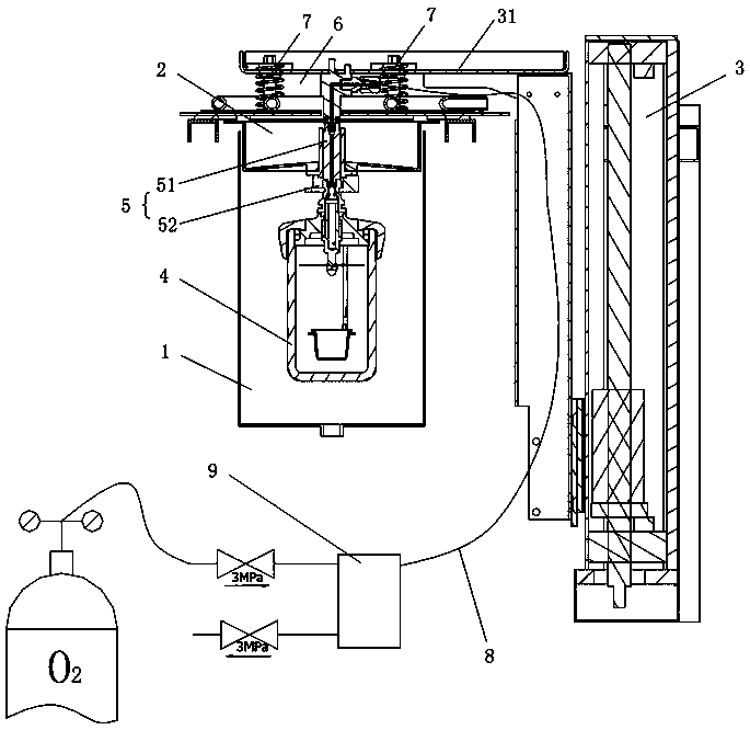
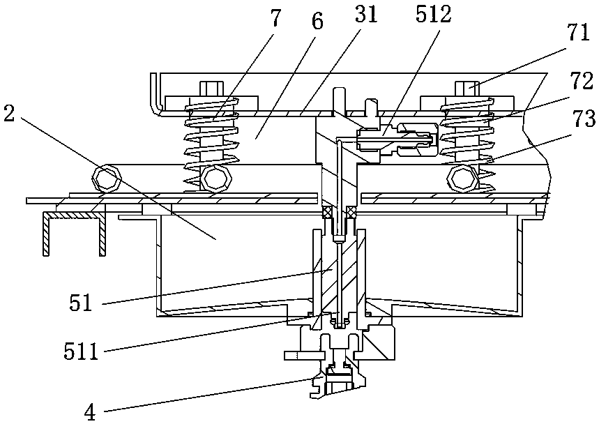
[0042] Such as Figure 2 to Figure 6 As shown, the present invention provides an automatic calorimeter for analyzing the calorific value of samples, including an inner barrel 1, a barrel lid 2, a barrel lid lifting mechanism 3 and an oxygen bomb 4, and the barrel lid lifting mechanism 3 drives the barrel lid 2 to lift to complete the inner barrel 1, the bung 2 is provided with an oxygen charging and discharging mechanism 5, and the bung lifting mechanism 3 is provided with a horizontally arranged lifting plate 31, and the bung 2 is movably connected to the bottom of the lifting plate 31, and the oxygen charging and discharging mechanism 5 The upper end is in the movable interlayer 6 between the lifting plate 31 and the bung 2. The lifting plate 31 drives the bung 2 to descend. Movable interlayer 6, now lifting plate 31 will continue to p...


PUM


Abstract

An automatic calorimeter for calorific value analysis of a sample comprises an inner barrel (1), a barrel cover (2), a barrel cover lifting mechanism (3), and an oxygen bomb (4). The barrel cover lifting mechanism (3) drives the barrel cover (2) to rise and fall so as to open and close the inner barrel (1), an oxygen charging and discharging mechanism (5) is disposed on the barrel cover (2), a transversely-disposed rising and falling plate (31) is disposed on the barrel cover lifting mechanism (3), the barrel cover (2) is movably connected below the rising and falling plate (31), and the upper end of the oxygen charging and discharging mechanism (5) is located in a movable sandwich layer (6) between the rising and falling plate (31) and the barrel cover (2). After the rising and falling plate (31) drives the barrel cover (2) to fall so as to complete covering, and the rising and falling plate (31) continuously presses to drive the oxygen charging and discharging mechanism (5) to be in downward contact with the oxygen bomb (4) and then carry out oxygen charging and discharging operation. The automatic calorimeter has the advantages of simple and compact structure, small size, low costs, easiness in maintenance and good gas charging and discharging effect.

Description

technical field [0001] The invention mainly relates to the field of sample analysis instruments, in particular to an automatic calorimeter used for calorific value analysis of samples. Background technique [0002] For the laboratory analysis of material (such as ore, coal) samples, each country has mandatory standards, which must be followed. For example, taking the analysis of coal samples as an example, the principle of the sample analysis process is to conduct relevant analysis on the samples that meet the requirements without destroying the representativeness of the samples. The accuracy of the analysis, so that the test results can reflect the characteristics of the sample most truly. [0003] In the laboratory analysis of material (such as ore, coal) samples, it is often necessary to use a calorimeter to analyze the calorific value of the sample. Such as figure 1 As shown, the existing calorimeter often has the following technical problems: [0004] 1. The oxygen ...

Claims


Application Information

Patent Timeline
Patent Type & Authority Patents(China)
IPC IPC(8): G01N25/20
CPCG01N25/20
Inventor 朱先德吴成乞胡亚军
Owner HUNAN SUNDY SCI & TECH DEV
Why Eureka
Try Eureka