A Large Range Transient Current Sensor Based on Tunneling Magnetoresistance

A technology of tunneling reluctance and transient current, which is applied in the field of sensing and measurement, can solve the problems of high preparation cost, limited installation space, and consumption of metal resources, and meet the requirements of wire thickness and number of turns flexibly, and is easy to debug and install The effect of maintaining and weakening the air gap magnetic field

Active Publication Date: 2018-08-10
TSINGHUA UNIV
View PDF8 Cites 0 Cited by
  • Summary
  • Abstract
  • Description
  • Claims
  • Application Information

AI Technical Summary

Problems solved by technology

In view of the development needs of the smart grid, the existing current transformers have great limitations: they are large in size, and the installation space on transmission and distribution lines and busbars is extremely limited; Not economical enough; single function, only suitable for power frequency AC signals, unable to measure DC, transient and high-order harmonics, etc.
Since the open magnetic ring 1 has the function of converging the magnetic field, the use of the open magnetic ring 1 further improves the sensitivity of the current probe, but reduces the current measurement upper limit of the current probe, and the traditional tunneling reluctance current sensor is very easy to saturate when measuring large currents
In addition, the use of the magnetic ring makes the chip in the air gap of the magnetic ring vulnerable to damage when measuring large currents, which limits the popularization and use of tunneling magnetoresistive current sensors

Method used


Image

  • A Large Range Transient Current Sensor Based on Tunneling Magnetoresistance
  • A Large Range Transient Current Sensor Based on Tunneling Magnetoresistance
  • A Large Range Transient Current Sensor Based on Tunneling Magnetoresistance

Examples


Embodiment Construction

[0017] A large-range transient current sensor based on tunneling magnetoresistance proposed by the present invention will be further described in detail in conjunction with the accompanying drawings and specific embodiments as follows:

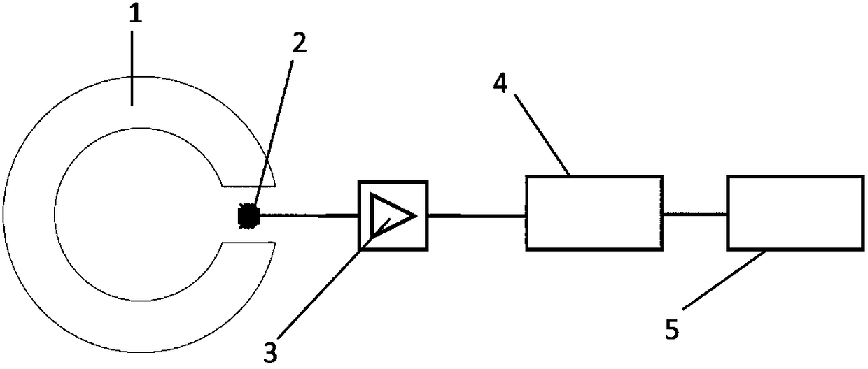
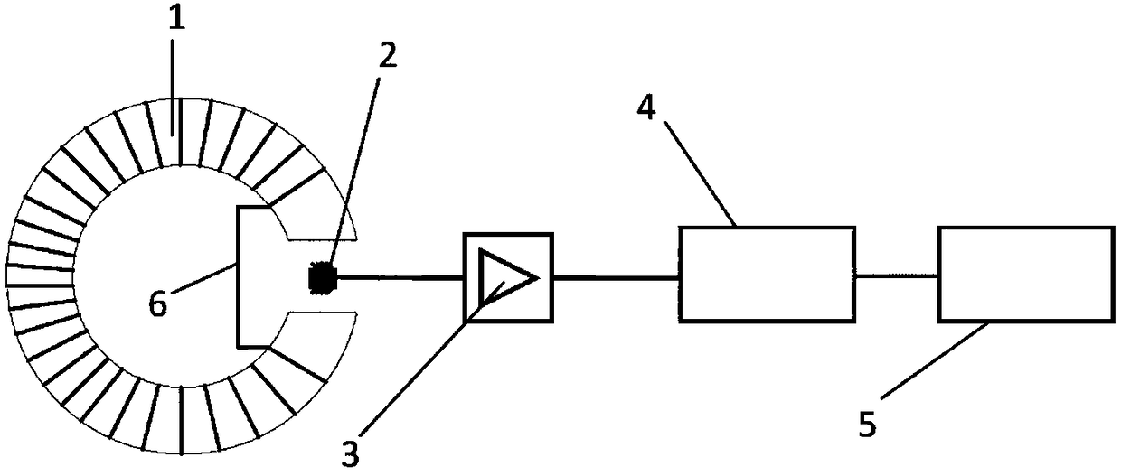
[0018] The large-range transient current sensor based on tunneling magnetoresistance proposed by the present invention has a structure such as figure 2 As shown, it includes: split magnetic ring 1, tunneling magnetoresistive magnetic sensor chip 2, signal conditioning circuit 3 (including instrument amplifier and power supply), analog-to-digital conversion device 4, data processing device 5 (compared with traditional tunneling magnetoresistive current The sensor device has the same composition structure); on this basis, it also includes a closed coil 6; wherein, the closed coil 6 is wound on the open magnetic ring 1 to expand the current measurement range; the tunneling at the opening of the open magnetic ring 1 The magnetoresistive magnetic ...


PUM


Abstract

The invention relates to a wide-range transient current sensor based on tunneling magnetic resistance, and belongs to the field of sensing measurement. The current sensor comprises an open magnet ring, a magnetic sensing chip of tunneling magnetic resistance, a signal conditioning circuit, a analog-to-digital converter, a data processing device and a closed coil, wherein the open magnet ring, the closed coil wound around the open magnet ring, the magnetic sensing chip of tunneling magnetic resistance in an opening of the open magnet ring and the signal conditioning circuit connected with the magnetic sensing chip of tunneling magnetic resistance form a current probe, and the signal conditioning circuit, the analog-to-digital converter and the data processing device are connected electrically successively. The thickness of the closed coil and the turn number of the wound coil, as parameters of the closed coil, are obtained by measurement and calculation, and enable that the possible maximal magnetic induction intensity, in an air gap of the open magnet ring, does not exceed the saturated magnetic induction intensity of the tunneling magnetic resistance chip. According to the invention, the range of the tunneling magnetic resistance sensor is broadened, requirement for current measurement of a power system is met, the sensitivity is high, damage tends not to occur, the cost is low and installation and maintenance are convenient.

Description

technical field [0001] The invention belongs to the field of sensor measurement, and in particular relates to greatly increasing the current upper limit value measured by a current probe by using coil damping, and constructing a large-range transient current sensor based on tunneling magnetoresistance. Background technique [0002] In recent years, the wave of smart grid has swept the world, and it has become a major research topic for global energy development and transformation in the current low-carbon and high-efficiency economy era. In order to realize real-time monitoring and control of the smart grid, advanced sensing and measurement technologies need to be developed urgently. [0003] Among the many electrical parameters of the smart grid, the requirements for current measurement are more diverse, and there are huge differences in the amplitude, frequency, sensitivity, and accuracy requirements of the measurement signal in different application scenarios: the current...

Claims


Application Information

Patent Timeline
Patent Type & Authority Patents(China)
IPC IPC(8): G01R19/25
CPCG01R19/25
Inventor 胡军王中旭欧阳勇赵帅何金良
Owner TSINGHUA UNIV
Why Eureka
Try Eureka