X-ray tube

An X-ray tube and cathode technology, applied in the field of X-ray tubes, can solve problems such as leakage of X-ray tubes, and achieve the effect of suppressing punch-through discharge

Active Publication Date: 2016-10-12
CANON ELECTRON TUBES & DEVICES CO LTD
View PDF5 Cites 2 Cited by
  • Summary
  • Abstract
  • Description
  • Claims
  • Application Information

AI Technical Summary

Problems solved by technology

If the penetration discharge of the insulator occurs, i...

Method used


Image

  • X-ray tube
  • X-ray tube
  • X-ray tube

Examples


Embodiment Construction

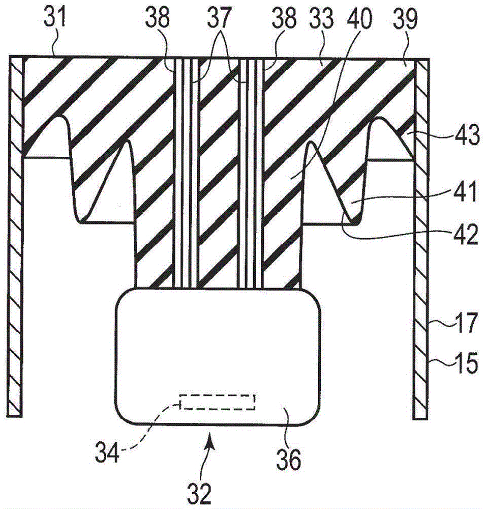
[0017] According to an embodiment, an X-ray tube according to the present invention includes: a vacuum envelope; and an anode and a cathode structure disposed opposite to each other within the vacuum envelope. The cathode structure includes: a cathode; and an insulator that supports the cathode and is installed in the vacuum envelope. The insulator has: a base attached to the vacuum envelope; a supporting portion protruding from the base to support the cathode at its tip; and a cylindrical protrusion protruding from the base and facing the periphery of the supporting portion. .

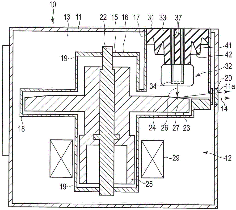
[0018] Below, refer to Figures 1 to 8B Embodiments will be described.

[0019] figure 2 An X-ray tube device 10 is shown. The X-ray tube device 10 includes: a casing 11 ; and an X-ray tube 12 arranged in the casing 11 . The X-ray tube 12 is an anode-grounded type X-ray tube and is a rotating anode type X-ray tube. The anode potential is ground potential. The space between the housing 11 and t...


PUM


Abstract

According to one embodiment, an X-ray tube includes a vacuum envelope (15), an anode and a cathode structure (31), which are provided opposite to each other in the envelope. The cathode structure includes a cathode (32) and an insulator (33) which supports the cathode and is attached to the vacuum envelope. The insulator includes a basal portion (39) attached to the vacuum envelope, a support portion (40) which supports the cathode at a distal end projecting from the basal portion, and a tubular projection portion (41) which is provided to project from the basal portion and opposite to a periphery of the support portion.

Description

technical field [0001] The present invention relates to X-ray tubes. Background technique [0002] Conventionally, X-ray tubes have been used in various applications such as medical diagnostic equipment. In the X-ray tube, a cathode and an anode are arranged facing each other in a vacuum envelope, and electrons released from the cathode collide with the anode to generate X-rays. In an anode-grounded X-ray tube, the cathode is supported in a vacuum envelope using an insulator such as ceramics. [0003] Furthermore, when an X-ray tube is used, if an electron avalanche occurs against an insulator, a penetration discharge through the insulator occurs, which causes failure of the X-ray tube. [0004] The electron avalanche relative to the insulator refers to: using electric field radiation to release electrons from the cathode, the released electrons follow the electric field to transition to the positive side (high potential side), the transitioned electrons collide with the i...

Claims


Application Information

Patent Timeline
IPC IPC(8): H01J35/16H01J35/06
CPCH01J35/06H01J35/16H01J2235/02
Inventor 渡边未树阿武秀郎石原智成
Owner CANON ELECTRON TUBES & DEVICES CO LTD
Why Eureka
Try Eureka