
Manufacturing method of array substrate, array substrate and display device

A manufacturing method and array substrate technology, applied in semiconductor/solid-state device manufacturing, instruments, semiconductor devices, etc., can solve problems such as increasing production costs and reducing production efficiency, and achieve the effects of improving manufacturing efficiency, preventing short circuits, and reducing production costs

Active Publication Date: 2018-11-13
BOE TECH GRP CO LTD
View PDF5 Cites 0 Cited by
  • Summary
  • Abstract
  • Description
  • Claims
  • Application Information

AI Technical Summary

Problems solved by technology

[0011] From the above description, it can be seen that at least 5 patterning processes are required to manufacture an array substrate using E-ADS, that is, at least 5 masks are required. The number of masks used in the above manufacturing process is relatively large, and each mask is used It must be precisely aligned with the substrate substrate at all times, which will reduce production efficiency and increase production cost

Method used


Image

  • Manufacturing method of array substrate, array substrate and display device
  • Manufacturing method of array substrate, array substrate and display device
  • Manufacturing method of array substrate, array substrate and display device

Examples


Embodiment Construction

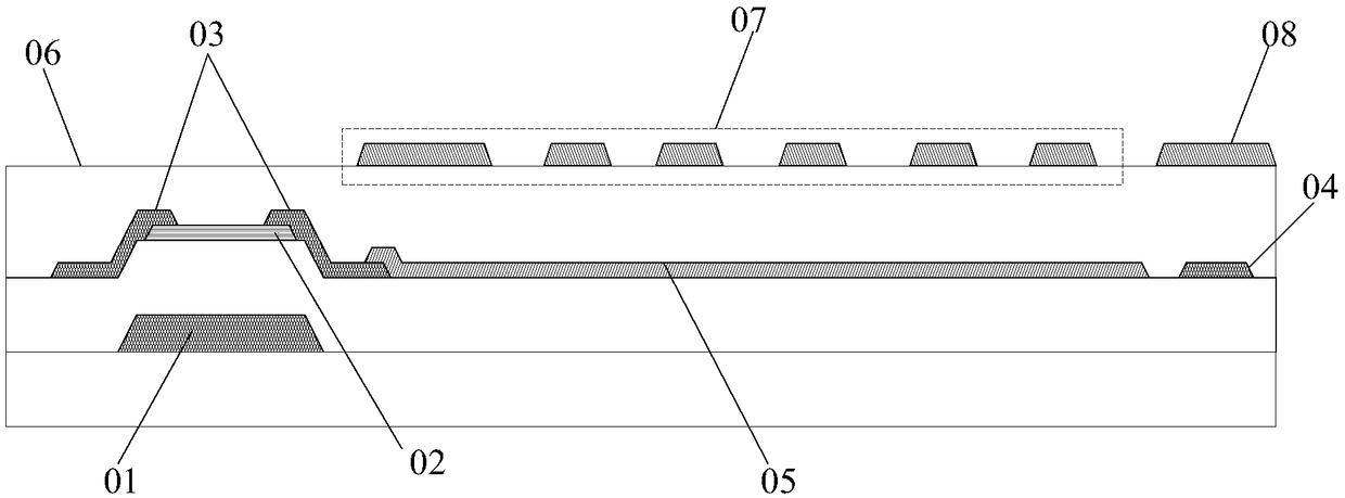
[0050] The method for fabricating the array substrate, the implementation of the array substrate and the display device provided by the embodiments of the present invention will be described in detail below with reference to the accompanying drawings.

[0051] The thickness and area size and shape of each layer of film in the drawings do not reflect the real proportion of the array substrate, but are only intended to schematically illustrate the content of the present invention.

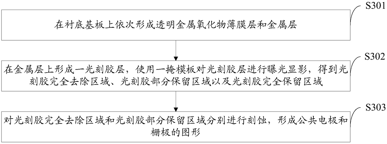
[0052] An embodiment of the present invention provides a method for manufacturing an array substrate, such as figure 2 As shown, it specifically includes the following steps:

[0053] S201, forming patterns of common electrodes and gates located in adjacent film layers on the base substrate through a patterning process;

[0054] S202, sequentially forming a pattern of a gate insulating layer, an active layer, a source / drain electrode, a data line, an insulating layer, and a pixel electrode on the p...


PUM


Abstract

The invention discloses a method for fabricating array substrate, an array substrate and a display device. In the invention, the film layer position of a common electrode in the array substrate is changed so as to facilitate the use of a one-time patterning process to form patterns of a common electrode and a grid on an adjacent film layer. This saves a production process, helps reduce the number of patterning processes in production, improves the production efficiency of the array substrate and cuts production cost. In addition, when the patterns of the grid and the common electrode are provided sequentially with patterns of a grid insulating layer, an active layer, a source layer, a drain electrode and data line, an insulating layer and a pixel electrode, the pixel electrode as well as the drain electrode and data line are located in different film layers, meaning that the pixel electrode needs go through the first through hole of the insulating layer before being connected to the source electrode of the drain electrode so as to prevent the short circuit that might arise in the case that the pixel electrode and the data line are located on an adjacent film layer and to reduce the parasitic capacitance between the data line and the pixel electrode.

Description

technical field [0001] The present invention relates to the field of display technology, in particular to a method for manufacturing an array substrate, the array substrate and a display device. Background technique [0002] Liquid Crystal Display (LCD) has the advantages of light weight, thin thickness, low power consumption, easy to drive, and no harmful rays. It has been widely used in modern information equipment such as TVs, notebook computers, mobile phones, and personal digital assistants. Has broad development prospects. [0003] An LCD is generally composed of an array substrate, an opposite substrate, and a liquid crystal layer placed between them. Electrodes are arranged on the inner side between the array substrate and the opposite substrate. After the electrodes are energized, an electric field will be generated between the array substrate and the opposite substrate, thereby affecting the arrangement of liquid crystals in between, blocking or twisting the passi...

Claims


Application Information

Patent Timeline
Patent Type & Authority Patents(China)
IPC IPC(8): H01L27/12H01L21/77G02F1/1362
CPCG02F1/136227H01L27/124H01L27/1288
Inventor 崔贤植田允允
Owner BOE TECH GRP CO LTD
Learn More