LED packaging structure and forming method thereof

A technology of LED packaging and LED chips, applied in electrical components, electrical solid devices, circuits, etc., can solve the problems of easy oxidation of fluorescent grease, affecting the service life of devices, accelerated aging, etc., to optimize the uniformity of light output and improve the use of Longevity, avoid the effect of easy oxidation

Active Publication Date: 2016-10-12
宁波协源光电科技股份有限公司
View PDF6 Cites 3 Cited by
  • Summary
  • Abstract
  • Description
  • Claims
  • Application Information

AI Technical Summary

Problems solved by technology

[0003] The current LED packaging is mainly a COB (chip on board) packaging structure, that is, the LED is fixed on the substrate by bonding wires, and then packaged with fluorescent glue, but it has the following disadvantages: 1) The fluorescent glue can be used in complex outdoor (long-term Sun exposure, ultraviolet rays, acid rain, hail, bird feces acid-base corrosion) or long-term high temperature conditions, there are problems such as easy aging, which will seriously affect the service life of de

Method used


Image

  • LED packaging structure and forming method thereof
  • LED packaging structure and forming method thereof
  • LED packaging structure and forming method thereof

Examples


Embodiment Construction

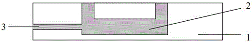
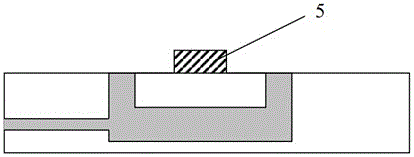
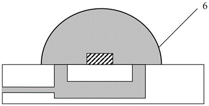
[0028] see Figure 4 , 5 The LED packaging structure of the present invention includes a heat dissipation substrate 1, an LED chip 5 arranged on the heat dissipation substrate 1, and a transparent cover 6 for sealing the LED chip 5, the transparent cover 6 and the heat dissipation substrate 1 The heat dissipation substrate 1 has a heat dissipation channel 2 inside, and the heat dissipation channel 2 communicates with the enclosed space, and the heat dissipation channel 2 and the enclosed space are filled with a fluid 8, and the fluid 8 can It is a colloid in which fluorescent powder is evenly distributed, and the fluid 8 may also be a liquid in which metal particles and / or fluorescent powder are dispersed, and the dispersion medium is oil. Wherein, said transparent cover body 6 can be glass or plastic etc., and its shape is hemispherical (such as Figure 4 shown), ellipsoidal or square (as Figure 6 shown), the heat dissipation channel 2 communicates with the enclosed space...


PUM


Abstract

The invention relates to an LED packaging structure comprising a cooling substrate, an LED chip arranged on the cooling substrate, and a transparent cover sealing the LED chip. A closed space is formed between the transparent cover and the cooling substrate. The LED packaging structure is characterized in that the cooing substrate is internally provided with a cooling channel which is communicated with the closed space, and the cooling channel and the closed space are filled with fluid. A forming method of the LED packaging structure is further disclosed. Oxidation of leads and welding points and aging of fluorescent resin are prevented, the cooling effect of the packaging structure is ensured, and the uniformity of light output is optimized.

Description

technical field [0001] The invention relates to the field of solid-state lighting materials, in particular to an LED packaging structure and a forming method thereof. Background technique [0002] LED is a solid-state semiconductor device that can directly convert electrical energy into light energy. Compared with traditional incandescent lamps and fluorescent lamps, white LEDs have the advantages of low power consumption, high luminous efficiency, long service life, energy saving and environmental protection, so they can not only be widely used in the field of daily lighting, but also enter the field of display equipment. [0003] The current LED packaging is mainly a COB (chip on board) packaging structure, that is, the LED is fixed on the substrate by bonding wires, and then packaged with fluorescent glue, but it has the following disadvantages: 1) The fluorescent glue can be used in complex outdoor (long-term Sun exposure, ultraviolet rays, acid rain, hail, bird feces a...

Claims


Application Information

Patent Timeline
IPC IPC(8): H01L33/48H01L33/50H01L33/58H01L33/64
CPCH01L2224/48091H01L2924/181H01L33/641H01L33/48H01L33/507H01L33/58H01L33/642H01L33/648H01L2933/0033H01L2933/0075H01L2933/0091
Inventor 王培培
Owner 宁波协源光电科技股份有限公司
Why Eureka
Try Eureka