
A semiconductor laser cavity surface coating jig assembly structure and assembly method thereof

An assembly structure and laser technology, which is applied in the direction of semiconductor lasers, lasers, laser components, etc., can solve problems such as difficult to hold bars, stable stacking, high processing precision, clamp expansion and jamming, etc., to achieve long-term coating use , Improve production efficiency, increase the effect of loading capacity

Active Publication Date: 2022-02-25
XIAN LIXIN PHOTOELECTRIC SCI & TECH
View PDF6 Cites 0 Cited by
  • Summary
  • Abstract
  • Description
  • Claims
  • Application Information

AI Technical Summary

Problems solved by technology

The disadvantage of this solution is: in order to prevent the bars from falling during the coating process, it is necessary to squeeze the stacked bars to fix them after the stacking is completed. The more bars there are, the greater the force required for extrusion and fixing. , and the easier it is to cause the rupture of the bars, which greatly limits the number of stacked bars
[0005] 1. Low chip utilization: the bar used for coating must be longer than the actual laser bar to be stuck in the coating fixture. After the coating is completed, it must be cut off, resulting in a high-quality growth part of the epitaxial wafer low wafer utilization;
[0006] 2. The process of the laser is complicated: before the coating process, the bar of the laser must be divided into a shape with a fixed length and width by a cleavage machine to meet the needs of the coating process; The two ends of the bar are cut off and cleaved to the size required by the final product, which increases the production process, and multiple cleavages are likely to cause damage to the laser bar and reduce the yield;
[0007] 3. The fresh side cavity surface has no protection in the packaging test, and the risk of leakage is high, which will cause the laser to burn out; the side of the finished laser bar formed by the final cleavage is directly exposed to the atmospheric environment, and it will be packaged into a device Finally, long-term work will generate a lot of heat, which will cause the metal solder of the package to wet to the side of the laser and contact the exposed laser body material
[0009] (1) This fixture needs to hold a certain number of bars, otherwise the fixture cannot complete the stacking function
In the specific implementation process, according to the inconsistent number of loaded bars, the pressure of the stacked bars will be inconsistent. If the load is too much and the pressure is too high, the bars may be damaged, and it is easy to cause the stacked bars to burst to one side and cause scrapped
[0010] (2) There is no anti-coating covering part. In the actual operation process, it is inevitable that the coating material will enter the groove frame. Long-term use is not conducive to the cleaning of the coating frame and the matching movement of the sliding block.
[0011] (3) The adaptability to bars of different widths is poor. If there is a large difference in cavity length, the height difference caused by bars of different widths needs to be compensated in the subsequent coating process steps, and the operability is poor.
[0012] (4) The requirements for machining accuracy are relatively high, which is not easy to achieve
There are many sliding fit parts, too tight fit, it is not easy to carry out the stacking process, and it is easy to cause the expansion and jamming of the fixture during the coating process, which will damage the bar in severe cases; too loose fit, it is not easy to hold the bar The stability of the bar stack, causing the bar stack to loosen
[0013] (5) The auxiliary tool for loading the strips is a flat plate, which is not conducive to the completion of the operation of the loading strips process, and the strips may be dumped
It is impossible to make the surface of the guide rail for auxiliary loading bars smaller. No matter whether the cleaning is clean or not, the cavity surface of the bars may be polluted during the process of loading bars, and the bars will eventually be scrapped.

Method used


Image

  • A semiconductor laser cavity surface coating jig assembly structure and assembly method thereof
  • A semiconductor laser cavity surface coating jig assembly structure and assembly method thereof
  • A semiconductor laser cavity surface coating jig assembly structure and assembly method thereof

Examples


Embodiment Construction

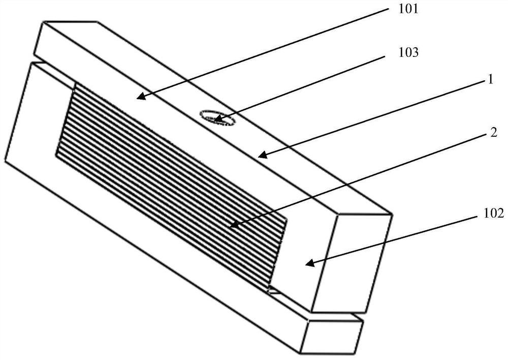
[0054] Such as figure 1 As shown, the stacked stacked bars are enclosed by a pair of discrete L-shaped structural parts to form a rectangular frame. The stacked bars are filled in the rectangular frame, and the stacked bars are stacked by these two structural parts. The strips are fixed by flat crimping; the rectangular frame maintains a gap with the side cavity of the filled strips. One of the L-shaped structural members (the L-shaped structural member facing outward when stacked) is provided with a blind hole on the outer crimping surface to facilitate the spring top wire assembly (such as image 3 Shown) the end is in reliable contact with the Dieba filling module.

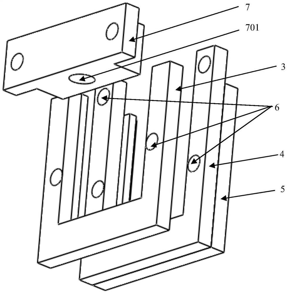
[0055] Such as figure 2 As shown, the main body of the limit fixing module is a flat U-shaped frame structure, which is specifically divided into a U-shaped upper plate, a U-shaped middle plate and a U-shaped lower plate; wherein, the U-shaped lower plate and the U-shaped upper plate are vertically The dire...


PUM


Abstract

The invention provides an assembly structure and an assembly method of a semiconductor laser cavity surface coating fixture, which is stable in clamping, simple and flexible in assembly, convenient in cleaning, and easy in mass production. The assembly structure of the coating fixture includes a stack filling module, a limit fixing module and a bearing table; the stack filling module is surrounded by two separate structural parts to form a non-closed rectangular frame, and the main body of the limit fixing module is a flat plate U-shaped frame structure, from the U-shaped closed end to the U-shaped open end, several stacked filling modules are arranged in sequence along the stacking direction of the strips, and the position on the stacked filled module that is in limited contact with the flat U-shaped frame structure is The part of the rectangular frame opposite to the plane of the side cavity of the loaded bar; the bearing platform is provided with a two-wing table corresponding to the flat U-shaped frame structure, and a fixed tensioner is installed in parallel above the relative concave area between the two-wing table. A number of load-bearing wires are used to support the stacked bars in the stacking module during assembly.

Description

technical field [0001] The invention relates to a novel semiconductor laser cavity surface coating jig assembly structure. Background technique [0002] In order to achieve high-power laser output, semiconductor lasers need to be coated with anti-reflection coatings and high-reflection coatings on the front and rear cavity surfaces, respectively. Conventional coating schemes are mainly divided into two categories: [0003] 1. Cleavage the semiconductor laser chip into strips and sandwich them vertically between two metal sheets. The disadvantage of this solution is: in order to prevent the bars from falling during the coating process, it is necessary to squeeze the stacked bars to fix them after the stacking is completed. The more bars there are, the greater the force required for extrusion and fixing. , and the easier it is to cause the rupture of the bars, which greatly limits the number of stacked bars. [0004] 2. Cleavage the semiconductor laser chip into strips and ...

Claims


Application Information

Patent Timeline
Patent Type & Authority Patents(China)
IPC IPC(8): H01S5/028
CPCH01S5/028
Inventor 李宁宋克昌杨国文
Owner XIAN LIXIN PHOTOELECTRIC SCI & TECH
Learn More