
Single-module drive circuit for multiple pulsed lamps

A technology for driving circuits and pulse lamps, which is applied to electric light sources, electrical components, light sources, etc., can solve the problems of high procurement cost, increased cost, and large actual usage of drive circuit modules, and achieves simplified control and maintenance costs and reduced production. and cost of use, ease of use and assembly, and the effect of

Active Publication Date: 2018-10-26
常州市兰诺光电科技有限公司
View PDF4 Cites 0 Cited by
  • Summary
  • Abstract
  • Description
  • Claims
  • Application Information

AI Technical Summary

Problems solved by technology

Due to the high purchase cost of the drive circuit module and the large actual usage of the module, the manufacturing and use costs of the entire pulsed strong light sterilization device are relatively high
[0004] In addition, after the number of drive circuit modules increases, it also increases the difficulty of controlling the pulse lamp, increases the connection between modules, and increases the connection between modules and lamps, making the structure of the product more complex and reducing Improve the efficiency of production and further increase the cost of the product

Method used


Image

  • Single-module drive circuit for multiple pulsed lamps
  • Single-module drive circuit for multiple pulsed lamps
  • Single-module drive circuit for multiple pulsed lamps

Examples


Embodiment Construction

[0041] The present invention will be further described below in conjunction with the accompanying drawings.

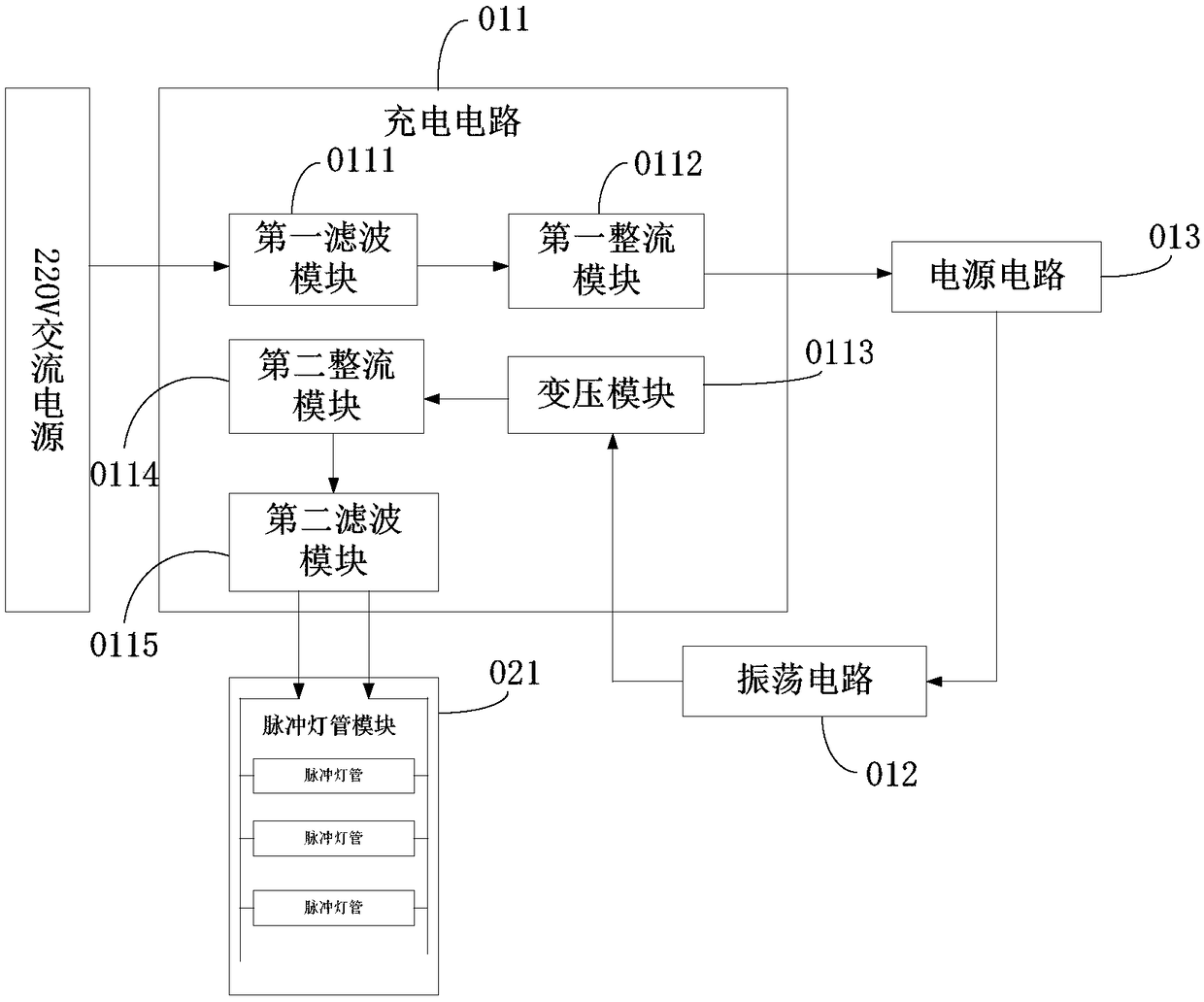
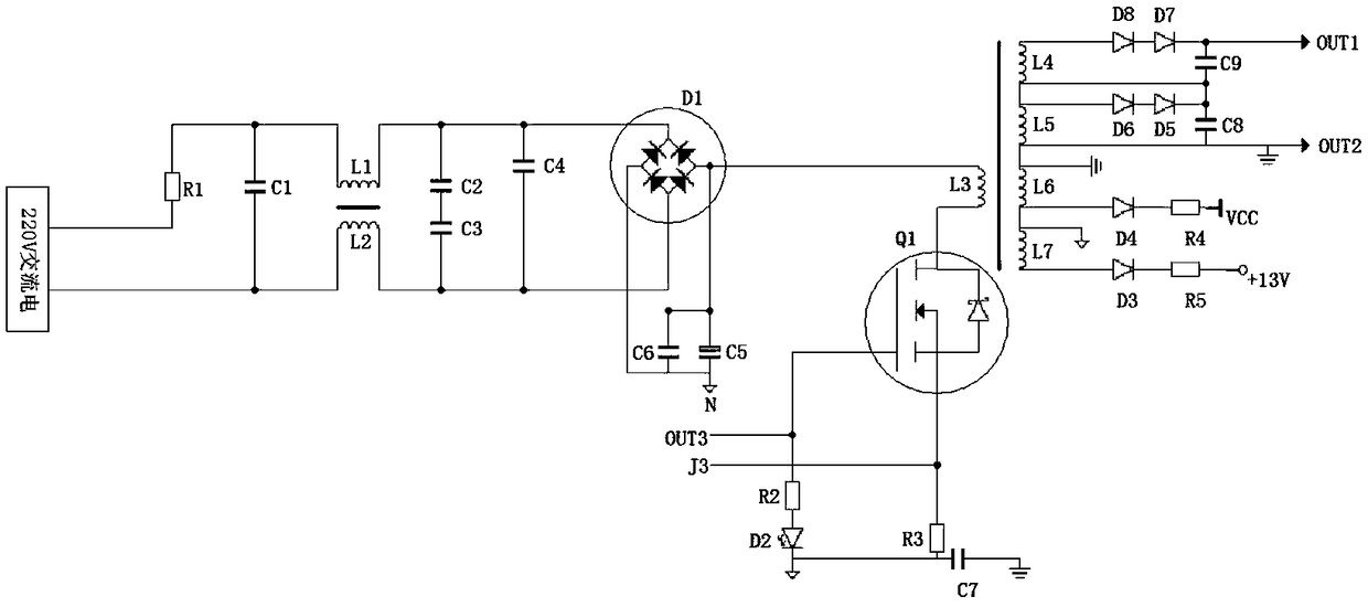
[0042] Such as figure 1 As shown, this solution includes a charging circuit 011, an oscillation circuit 012, and a power supply circuit 013; wherein, the charging circuit 011 includes a first filtering module 0111, a first rectifying module 0112, a transformer module 0113, a second rectifying module 0114, and a second filtering module module 0115;

[0043] After the 220V AC power is filtered and rectified by the first filter module 0111 and the first rectifier module 0112, a stable DC signal is output; the DC signal then passes through the joint action of the power supply circuit 013 and the oscillation circuit 012 to output a high frequency The pulse voltage signal is boosted by the transformer module 0113 to generate a high-voltage and high-frequency pulse voltage signal, and the high-frequency and high-voltage pulse voltage signal is rectified and filtered by the s...


PUM


Abstract

The charging circuit comprises a single-module driving circuit for a plurality of pulse lamps. The single-module driving circuit comprises a charging circuit, an oscillating circuit and a power supply circuit, wherein the charging circuit comprises a first filtering module, a first rectifying module, a voltage transformation module, a second rectifying module and a second filtering module; the first filtering module and the first rectifying module output a DC voltage signal; the DC voltage signal is converted into a high-voltage and high-frequency pulse voltage signal after passing through the power supply circuit, the oscillating circuit and the voltage transformation module; and the high-voltage and high-frequency pulse voltage signal passes through the second rectifying module and the second filtering module such that a stable DC pulse signal is output, and the DC pulse signal is loaded to both ends of the plurality of pulse lamps which are connected in parallel. The single-module driving circuit can drive the plurality of pulse lamp tubes simultaneously without additionally arranging a driving module, and greatly reduces the production and usage costs of pulse lamp equipment.

Description

technical field [0001] The invention relates to the technical field of pulsed strong light, in particular to a single-module drive circuit for multiple pulsed lamps. Background technique [0002] Pulse strong light technology is a kind of pulse engineering technology using instantaneous discharge and a special inert gas lamp tube to excite strong white light in the form of pulses. The spectral distribution is similar to sunlight, and the light intensity is equivalent to thousands or even Tens of thousands of times a world-leading light source technology. It uses instantaneous, high-intensity pulsed light energy to kill all kinds of microorganisms, thus making up for the shortcomings of traditional heat sterilization and chemical sterilization. [0003] The traditional pulse strong light sterilization device uses alternating current as the power supply and consists of a drive circuit module and a pulse lamp, that is, one drive circuit can only drive one pulse lamp. However,...

Claims


Application Information

Patent Timeline
Patent Type & Authority Patents(China)
IPC IPC(8): H05B41/30
CPCH05B41/30
Inventor 蒋栋刘璠
Owner 常州市兰诺光电科技有限公司
Learn More