Integrated high-rotation-speed swash-plate-rotating motor pump

A motor pump and rotary technology, which is applied in the direction of liquid variable displacement machinery, variable displacement pump components, liquid fuel engines, etc., can solve the problems of increased possibility of overturning of moving parts, low power factor and power density, and unreliable reliability. Improvement and other issues to achieve the effect of improving fault tolerance and reliability, reducing the difficulty of processing and assembly processes, and simplifying the structure

Active Publication Date: 2016-10-19
ZHEJIANG UNIV
View PDF7 Cites 8 Cited by
  • Summary
  • Abstract
  • Description
  • Claims
  • Application Information

AI Technical Summary

Problems solved by technology

[0003] The above-mentioned various schemes still have some deficiencies. Motor pumps using vane pumps or gear pumps (such as patent 200710305961.3 motor-embedded vane pumps) cannot be applied to high-pressure and high-speed working conditions, which limits the further improvement of power density; traditional forms Although the advanced axial piston pump can be applied to high-pressure and high-speed working conditions, due to the increase of oil absorption resistance and centrifugal force at high speeds, the possibility of overturning of moving parts such as cylinders and sliding shoes increases, and the rotor assembly Factors such as the large stirring loss of the oil in the stirri

Method used


Image

  • Integrated high-rotation-speed swash-plate-rotating motor pump
  • Integrated high-rotation-speed swash-plate-rotating motor pump
  • Integrated high-rotation-speed swash-plate-rotating motor pump

Examples


Embodiment Construction

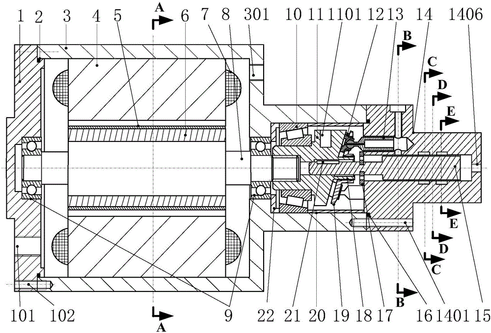
[0042] Attached below Figure 1 to Figure 9 The present invention will be further described with specific examples.

[0043] Such as figure 1 As shown, the present invention includes a motor pump housing 3 and a motor and a swash plate 11 integrally installed in the motor pump housing 3. The motor pump housing 3 is a structure connected by a large end housing and a small end housing. The end face of the end shell is installed with the end cover 1 through the threaded hole 102, and is sealed by the first sealing ring 2; the end face of the small end shell is installed with the rear pump body 14 through the threaded hole 1401, and is sealed by the second sealing ring 16; The large-end housing and the small-end housing are respectively provided with a large-end cavity and a small-end cavity. The large-end cavity and the small-end cavity are connected. A motor is installed in the large-end cavity, and a swash plate mechanism is installed in the small-end cavity. The motor and the...


PUM


Abstract

The invention discloses an integrated high-rotation-speed swash-plate-rotating motor pump. The integrated high-rotation-speed swash-plate-rotating motor pump comprises a motor pump shell, a five-phase fault-tolerant permanent-magnet brushless direct current motor and a swash plate, wherein the five-phase fault-tolerant permanent-magnet brushless direct current motor and the swash plate are integrally installed in the motor pump shell. The motor pump shell is of a structure formed by connecting a large-end shell and a small-end shell; an end cover is installed on the end face of the large-end shell, sealing is carried out through a sealing ring, and a back pump body is installed on the end face of the small-end shell; a large-end cavity in the large-end shell and a small-end cavity in the small-end shell are communicated, the five-phase fault-tolerant permanent-magnet brushless direct current motor and a swash plate mechanism are installed in the large-end cavity and the small-end cavity respectively, the motor is coaxially connected with the swash plate mechanism, and the swash plate rotates to drive a flow distribution shaft with one end extending into the back pump body to synchronously rotate. According to the integrated high-rotation-speed swash-plate-rotating motor pump, a swash-plate-rotating axial plunger pump and the five-phase fault-tolerant permanent-magnet brushless direct current motor are axially connected in series and integrated into the same shell, the radial size is greatly reduced, rotational inertia is reduced, and the dynamic response speed is increased; reliability and fault-tolerant capability are high, power density is further increased, and the integrated high-rotation-speed swash-plate-rotating motor pump and a hydraulic cylinder can be easily integrated.

Description

technical field [0001] The invention relates to an integrated high-speed motor pump, in particular to an integrated high-speed swash plate rotary motor pump. Background technique [0002] The motor pump is a motor-driven pump, that is, the motor is directly connected to the hydraulic pump through a spline without a coupling. It is a widely used hydraulic power unit. Since the 1990s, due to the need to further reduce the size of the hydraulic power unit and increase the power density, an integrated motor pump that combines the motor and the pump has appeared. The integration is mainly reflected in the direct connection between the plunger pump and the motor shaft, sharing a housing, or further fuse the motor rotor and the hydraulic pump rotor (the hydraulic pump rotor is nested into the motor rotor). The integrated design not only greatly improves the power density of the hydraulic power unit, but also reduces the noise of the power source, reduces the possibility of oil lea...

Claims


Application Information

Patent Timeline
IPC IPC(8): F04B17/03F04B1/14F04B53/08F04B53/00
CPCF04B1/14F04B1/141F04B1/145F04B1/146F04B17/03F04B53/08
Inventor 欧阳小平李磊王天照杨华勇
Owner ZHEJIANG UNIV
Why Eureka
Try Eureka