Continuous casting tundish breathable ceramic tube upper nozzle brick cup and argon blowing refining method thereof

A technology of continuous casting tundish and nozzle block, which is used in casting equipment, casting melt containers, manufacturing tools, etc., can solve the problems of small effect and unstable "annular airflow, etc., to promote floating and removal, and inhibit immersion." The effect of the nodule problem of the sprue

Active Publication Date: 2016-10-26
SHANDONG IRON & STEEL CO LTD
View PDF8 Cites 13 Cited by
  • Summary
  • Abstract
  • Description
  • Claims
  • Application Information

AI Technical Summary

Problems solved by technology

However, the disadvantages of this technology are: (1) Due to the continuous adhesion of oxides and other inclusions in the molten steel to the inner surface of the upper nozzle, coupled with the static pressure of the molten steel, as the amount of steel passing through the upper nozzle increases, the blown argon gas It is difficult to continue to pass through the inner wall surface of the upper nozzle, and the amount of argon gas entering the nozzle gradually decreases, forming an unstable "circular air flow" in the submerged nozzle, and the molten steel entering the mold is intermittently entrained with "big bubbles" into the mold , a small part of the argon bubbles move to the lower circulation area of ​​the crystallizer, and are captured by the inner surface of the solidified slab shell, and finally form the subcutaneous bubbles of the cast slab; (2) Argon bubbles blown through the inner wall of the upper nozzle enter the nozzle with the steel flow , argon bubbles have little effect on capturi...

Method used


Image

  • Continuous casting tundish breathable ceramic tube upper nozzle brick cup and argon blowing refining method thereof
  • Continuous casting tundish breathable ceramic tube upper nozzle brick cup and argon blowing refining method thereof
  • Continuous casting tundish breathable ceramic tube upper nozzle brick cup and argon blowing refining method thereof

Examples


Embodiment 1

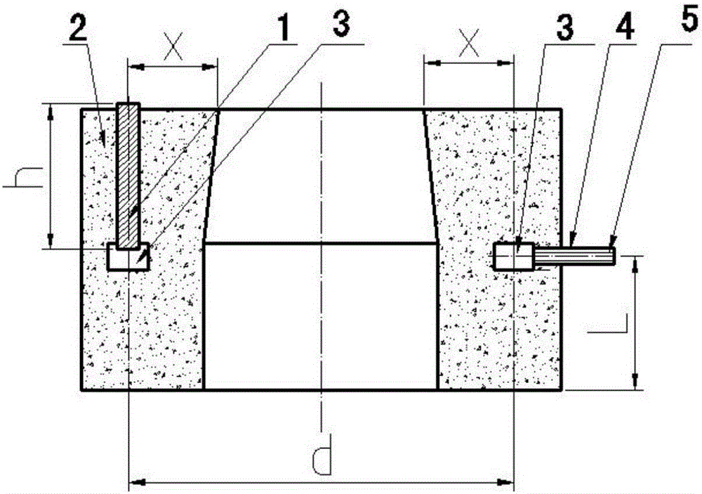
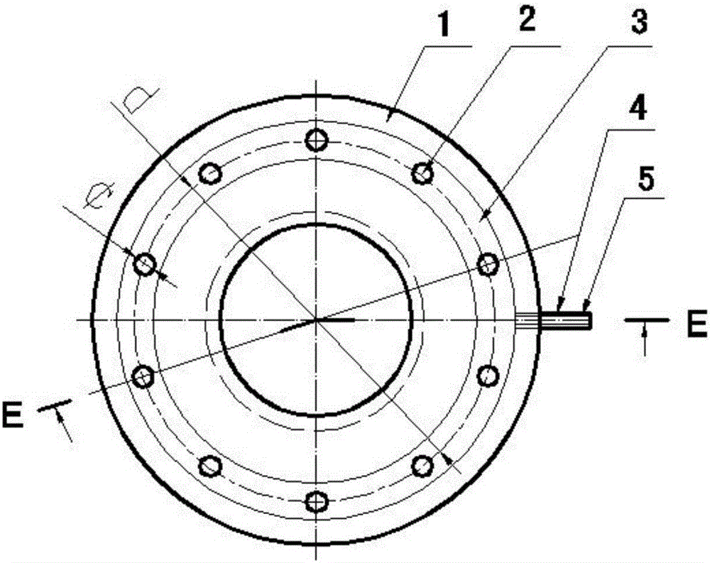
[0045] A continuous casting tundish breathable ceramic tube upper nozzle seat brick, such as figure 1 , figure 2 , image 3 , Figure 4 As shown, it includes the upper nozzle block body 1, the ceramic tube 2, the air chamber 3, and the air intake pipe 4. The middle part of the upper nozzle block body is provided with an upper nozzle installation hole that penetrates up and down, and the upper nozzle block body 1 is provided with a circle. A plurality of ceramic tubes 2 evenly arranged in the ring and a circular air chamber 3 are provided with a plurality of sockets 20 evenly arranged in a circular shape. The shape, quantity and arrangement of the sockets 20 are the same as the Corresponding to the ceramic tube 2, the top of the ceramic tube protrudes from the upper surface of the nozzle block body 1 by 5-10mm, the lower end of the ceramic tube 2 is fixed in the socket 20 on the air chamber, and communicates with the air chamber 3, the side of the air chamber Connected with...

Embodiment 2

[0063] The continuous casting tundish air-permeable ceramic tube upper nozzle seat brick as described in Example 1, the difference lies in:

[0064] The distance x between the longitudinal centerline of the ceramic tube 2 and the upper edge of the installation hole of the upper nozzle is 55mm.

[0065] The cylindrical outer diameter ¢ of the air-permeable ceramic tube 2 is 30 mm, and the height h of the ceramic tube is 125 mm.

[0066] The diameter of the blowing channel set in the breathable ceramic tube 2 is 0.16 mm, and the blowing channels are evenly distributed in 3 concentric rings. From the inside to the outside, the number of blowing channels in the first ring is 7, and the number of blowing channels in the second ring The number of blowing channels is 14, and the number of blowing channels in the third ring is 21.

[0067] There are 16 breathable ceramic pipes 2, which are uniformly arranged in a ring shape, and the distance x between the longitudinal centerline of t...

Embodiment 3

[0079] The continuous casting tundish air-permeable ceramic tube upper nozzle seat brick as described in Example 1, the difference lies in:

[0080] The distance x between the longitudinal centerline of the ceramic tube 2 and the upper edge of the installation hole of the upper nozzle is 50mm.

[0081] The cylindrical outer diameter ¢ of the air-permeable ceramic tube 2 is 18 mm, and the height h of the ceramic tube is 115 mm.

[0082] The diameter of the blowing channel set in the breathable ceramic tube 2 is 0.15 mm, and the blowing channels are evenly distributed in three concentric rings. From the inside to the outside, the number of blowing channels in the first ring is 6, and the number of blowing channels in the second ring is 6. The number of blowing channels is 12, and the number of blowing channels of the third ring is 18.

[0083] There are 12 breathable ceramic pipes 2, which are evenly arranged in a ring shape, and the distance x between the longitudinal centerli...


PUM

PropertyMeasurementUnit
Heightaaaaaaaaaa
Widthaaaaaaaaaa
Bulk densityaaaaaaaaaa

Abstract

The invention relates to a continuous casting tundish breathable ceramic tube upper nozzle brick cup and an argon blowing refining method thereof. The upper nozzle brick cup comprises an upper nozzle brick cup body, a plurality of ceramic tubes, a gas chamber and a gas inlet pipe, wherein the ceramic tubes are uniformly arranged in a circle; the ceramic tubes and the circular gas chamber are arranged in the upper nozzle brick cup body; a plurality of sockets are uniformly arranged on the gas chamber in a circle; the top ends of the ceramic tubes extend out of the upper surface of the upper nozzle brick cup body by 5 to 10 mm; the lower ends of the ceramic tubes are fixed in the sockets on the gas chamber, and communicate with the gas chamber; the gas inlet pipe is connected to one side part of the gas chamber, and communicates with an external argon gas source by being connected with a metal pipe fitting; an upward circular air curtain barrier is formed after argon gas is blown into the gas inlet pipe, so that gas washing of molten steel entering an upper nozzle is realized; and a certain quantity of argon bubbles enter the upper nozzle along with a steel flow, so that a stable and continuous circular gas flow is formed, which not only solves the problem of nozzle clogging, but also solves the technical problem that protective argon bubbles enter steel to cause sub-surface bubbles of a casting blank.

Description

technical field [0001] The invention relates to a continuous casting tundish breathable ceramic pipe upper nozzle seat brick and an argon blowing refining method thereof, belonging to the technical field of iron and steel metallurgy continuous casting tundish metallurgical technology. Background technique [0002] At present, low-carbon aluminum-killed steel and IF steel are produced by casting slab continuous casting machines. In order to solve the problem of nozzle nodulation, various steel mills generally adopt the method of blowing argon gas into the inner wall of the upper nozzle of the tundish. When the flow rate of argon gas entering the nozzle When the value is increased to a certain value, the gas will form an "annular airflow" in the nozzle, which can significantly reduce the problem of nodulation in the nozzle. However, the disadvantages of this technology are: (1) Due to the continuous adhesion of oxides and other inclusions in the molten steel to the inner surfa...

Claims


Application Information

Patent Timeline
IPC IPC(8): B22D41/58B22D11/117
CPCB22D11/117B22D41/58
Inventor 武光君王中学郭伟达
Owner SHANDONG IRON & STEEL CO LTD
Why Eureka
Try Eureka