
Twisted welding wire structure and manufacturing method thereof

A technology of stranded welding wire and manufacturing method, which is applied to the structure of stranded welding wire and its manufacturing field, can solve the problems of insufficient welding wire diameter, uneven welding quality, poor rigidity, etc., and achieves high deposition efficiency, low dilution rate, welding The effect of improving the quality of seam performance

Inactive Publication Date: 2016-10-26
梁裕
View PDF8 Cites 8 Cited by
  • Summary
  • Abstract
  • Description
  • Claims
  • Application Information

AI Technical Summary

Problems solved by technology

[0007] The technical problem to be solved by the present invention is to provide a twisted welding wire structure and its manufacturing method for the above-mentioned prior art, which can solve the problem that the diameter of the traditional welding wire is not large enough, it is not easy to coil when the diameter increases, the rigidity is poor, the energy consumption is high, the welding Low rate, uneven welding quality and other problems

Method used


Image

  • Twisted welding wire structure and manufacturing method thereof
  • Twisted welding wire structure and manufacturing method thereof
  • Twisted welding wire structure and manufacturing method thereof

Examples


Embodiment 1

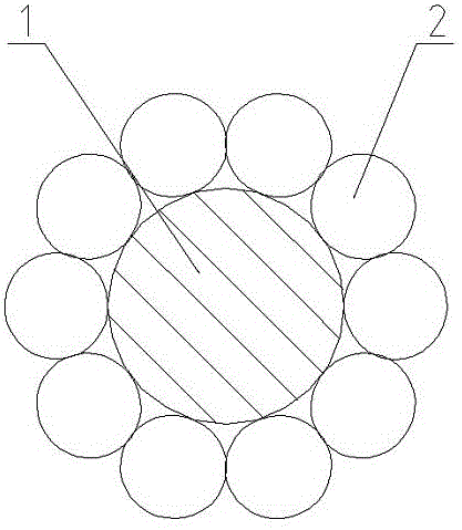
[0062] Example 1: 1+10 unequal diameter monofilament stranded carbon dioxide gas shielded stranded welding wire

[0063] In this embodiment, the central wire 1 adopts a flux-cored wire of φ1.0mm, the peripheral wire 2 adopts a solid cored wire of φ0.4mm, and the diameter of the stranded welding wire is φ1.8mm. Compared with the existing Φ1.2mm and Φ1.8mmΦ2.3mm carbon dioxide gas shielded solid welding wire, the welding deposition speed is faster, and it has the characteristics of high efficiency, high cost and low consumption.

[0064] The winding angle of the peripheral wire 2 is 25°, and the pitch of the helix is ​​9.43mm;

[0065] This stranded welding wire is a rope-like welding wire with multiple twists around a central wire. Under the protection of carbon dioxide gas, it has better flexibility than a single welding wire of equal diameter, and has a stable, stable, wide range of current, voltage waveform, and stable arc shape to ensure that the weldment has a reasonable ...

Embodiment 2

[0066] Implementation 2: 1+10 unequal diameter monofilament stranded submerged arc welding wire

[0067] In this embodiment, the central wire is φ3.2mm, the peripheral wire is φ1.4mm, and the diameter of the stranded welding wire is φ5.85mm. The diameter of this stranded welding wire is equivalent to φ0.60mm single-wire submerged arc welding wire, but its wire feeding flexibility is excellent. The unique arc characteristics of stranded welding wire reduce the welding current and voltage, and its central wire has a certain impact characteristic, which can ensure the penetration depth and realize the economical performance of high-efficiency and low-consumption welding.

[0068] The winding angle of the peripheral wire 2 is 30°, and the pitch of the helix is ​​25.0mm.

[0069] Its manufacturing method is as follows:

[0070] Step 1. Wind a single welding wire onto the I-shaped wheel assembly;

[0071] Step 2. Install multiple I-shaped wheel assemblies with single welding wires...


PUM


Abstract

The invention relates to a twisted welding wire structure and a manufacturing method thereof, which belong to the technical field of metal welding. The twisted welding wire structure comprises a center wire (1), wherein multiple strands of peripheral wires (2) are spirally twisted on the periphery of the center wire (1), the diameter of the center wire (1) is not equal to that of each peripheral wire (2), and the diameter ratio of the peripheral wires (2) to the center wire (1) is 0.40 to 0.77. According to the twisted welding wire structure and the manufacturing method thereof, the problems that the diameter of a traditional welding wire is not big enough, the traditional welding wire is not likely to be wound when the diameter is increased, the rigidity is poor, energy consumption is high, deposition rate is high, welding quality is uneven and the like can be solved.

Description

technical field [0001] The invention relates to a stranded welding wire structure and a manufacturing method thereof, belonging to the technical field of metal welding. Background technique [0002] Metal arc welding of steel is a traditional foundational technology in manufacturing. As a general common technology, welding is used as a key processing technology by a considerable number of enterprises in the manufacturing industry. [0003] According to the division method of my country's industry categories, these enterprises are widely distributed in boilers, pressure vessels, power generation equipment, nuclear facilities, petrochemicals, pipelines, metallurgy, mining, railways, automobiles, shipbuilding, port facilities, aerospace, construction, agricultural machinery , water conservancy facilities, construction machinery, machine manufacturing, medical equipment, precision instruments and electronics industries. These enterprises have a profound influence, involve a wid...

Claims


Application Information

Patent Timeline
Patent Type & Authority Applications(China)
IPC IPC(8): B23K35/08B23K35/40
CPCB23K35/0283B23K35/406
Inventor 梁裕吴文晨
Owner 梁裕
Learn More