Grinding method and grinding apparatus

A grinding and grinding technology, which is used in grinding drive devices, machine tools designed for grinding workpiece rotating surfaces, metal processing equipment, etc., can solve the problem of reduced compressor performance, increased mechanical loss, compressor wear, etc. problems, to achieve the effect of reducing surface roughness, inhibiting wear or sintering, and reducing manufacturing costs

Active Publication Date: 2016-10-26
MITSUBISHI ELECTRIC CORP
View PDF9 Cites 9 Cited by
  • Summary
  • Abstract
  • Description
  • Claims
  • Application Information

AI Technical Summary

Problems solved by technology

As a result, the compressor may be worn or sintered and cannot rotate smoothly
[0012] In addition, in the technique disclosed in Patent Document 2, the concave portion or the non-sliding portion of the thrust surface becomes a surface discontinuous from the flat portion, so that the formation of the oil film necessary for the thrust surface is interrupted, which may cause instability. abnormal noise due to the vibration of the crankshaft
In addition, since the thrust surface is formed as a simple plane, the mechanical loss caused by sliding friction or oil film agitation increases, which may lead to a reduction in compressor performance due to an increase in motor input.

Method used


Image

  • Grinding method and grinding apparatus
  • Grinding method and grinding apparatus
  • Grinding method and grinding apparatus

Examples


Embodiment approach 1

[0046] [Structure of Cylindrical Grinder 100]

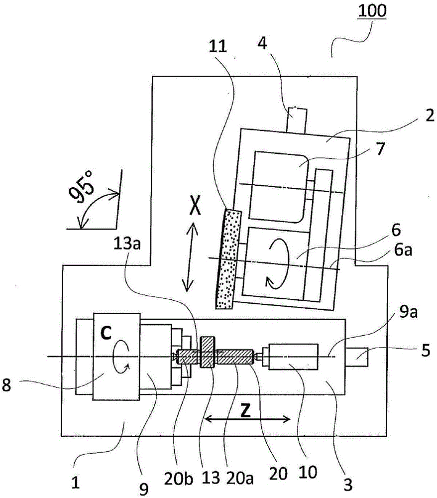
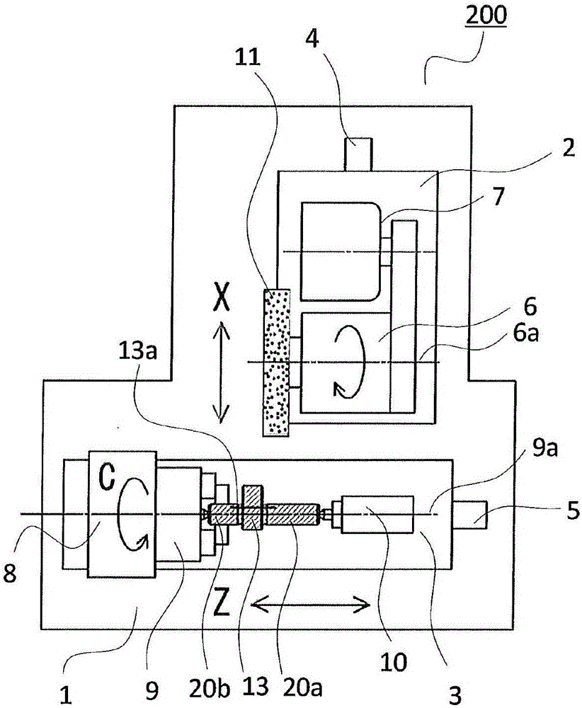
[0047] figure 1 It is a top view showing the structure of the cylindrical grinder 100 which concerns on this embodiment. In addition, the cylindrical grinder 100 corresponds to the "grinding device" of this invention.

[0048] based on figure 1 The structure of the cylindrical grinder 100 which concerns on this embodiment is demonstrated. The lathe bed 1 that constitutes the base of the cylindrical grinding machine 100 is equipped with: the X-axis table 2 and the grinding wheel conveying device 4 that guide the conveying (X axis) of the grinding wheel; and the conveying (Z axis) to the main shaft 8 axis) to guide the Z-axis table 3 and the Z-axis conveying device 5. The X-axis table 2 and the Z-axis table 3 that move on the guide surface on the bed 1 are equipped with a combination device of a servo motor and a ball screw or a linear motor device as a conveyance drive mechanism. A grinding wheel spindle 6 and a grinding whee...

Embodiment approach 2

[0089] Figure 14 It is a figure which shows the processing process of the cylindrical grinding machine 100 which concerns on this embodiment.

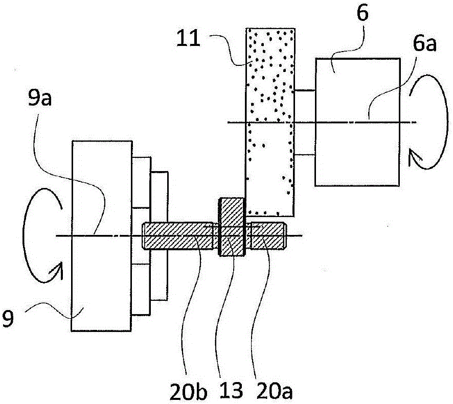
[0090] Such as Figure 14 As shown, a crankshaft is processed by using an external cylindrical grinder 100, and the crankshaft includes: a cylindrical major axis portion 20a and a minor axis portion 20b concentric with each other; and a cylindrical eccentric portion 13 formed on the major axis portion Between 20a and the short-axis portion 20b, there is a center offset from the centers of the long-axis portion 20a and the short-axis portion 20b. In addition, in Figure 14 The minor axis portion 20b is not shown in FIG. The cylindrical grinder 100 performs grinding of the outer diameter of the eccentric portion 13 , continuous micro-curved surface processing of the thrust surface 12 , and cylindrical transverse grinding of the major axis portion simultaneously. The "simultaneous processing" mentioned here means "using the same chuc...

Embodiment approach 3

[0103] Figure 19 It is a vertical cross-sectional view showing the configuration of a rotary compressor 50 for refrigeration and air-conditioning using the crankshaft 20 according to the present embodiment.

[0104] Figure 20 It is a sectional view showing the mechanism of the compression chamber of the rotary compressor 50 according to this embodiment.


PUM


Abstract

Provided are a grinding method and a grinding apparatus for forming a chosen continuous microscopically curved surface on the thrust surface of a shaft using a cylindrical grinder. In a cylindrical grinder provided with a main shaft for holding and rotating a cylindrical workpiece, a cylindrical grindstone for grinding the workpiece and a cylindrical grindstone feed shaft that moves the cylindrical grindstone in a parallel manner, the cylindrical grindstone feed shaft is disposed so that the angle of intersection with the rotation axis of the main shaft is greater than 90 degrees to 100 degrees or less. This grinding method comprises a step for synchronizing the rotational movement of the main shaft with the reciprocating movement of the cylindrical grindstone to form a chosen continuous microscopically curved surface on the thrust surface.

Description

technical field [0001] The present invention relates to a grinding method and a grinding device used in the grinding method. Background technique [0002] As surface machining methods of a shaft-shaped workpiece (object to be ground) by cylindrical grinding, there are the following two methods. The first method is to rotate a shaft-shaped workpiece while being held on a main shaft, and to bring the end surface of a cylindrical grinding wheel having a rotation axis parallel to the main shaft into contact with the workpiece. In addition, the second method is to hold and rotate a shaft-shaped workpiece on the main shaft, and bring the end face of the angular grinding wheel having a cross section at an angle intersecting the main shaft into contact with the workpiece. axis of rotation. The latter has the following cases: the case of using an angular head type cylindrical grinding machine configured to rotate the angle of the grinding wheel axis of the cylindrical grinding mach...

Claims


Application Information

Patent Timeline
Patent Type & Authority Applications(China)
IPC IPC(8): B24B5/04B24B5/35B24B47/20B24B41/04B24B1/00
CPCB24B5/42B24B11/06B24B47/20B24B5/04B24B1/00B24B5/35B24B41/04
Inventor 井沢毅司朴木继雄
Owner MITSUBISHI ELECTRIC CORP
Why Eureka
Try Eureka