Three-axis robot and arm and using method thereof

A robot arm and robot technology, applied in the field of robotics, can solve the problems of large volume, high manufacturing cost, complex structure, etc., and achieve the effect of small size, low manufacturing cost and simple operation

Active Publication Date: 2016-10-26
马鞍山工蜂智能科技有限公司
View PDF13 Cites 2 Cited by
  • Summary
  • Abstract
  • Description
  • Claims
  • Application Information

AI Technical Summary

Problems solved by technology

[0007] Aiming at the problems of complex structure, large volume and high manufacturing cost of existing robots for assembly and transfer, the present invention provides a three-axis robot, its arm and its use method, which have a simple and compact structure, small volume, low manufacturing cost and flexible movements , accurate, can replace the existing assembly and transfer robots with complex structures to achieve the effect of improving production efficiency and reducing production costs

Method used


Image

  • Three-axis robot and arm and using method thereof
  • Three-axis robot and arm and using method thereof
  • Three-axis robot and arm and using method thereof

Examples


Embodiment 1

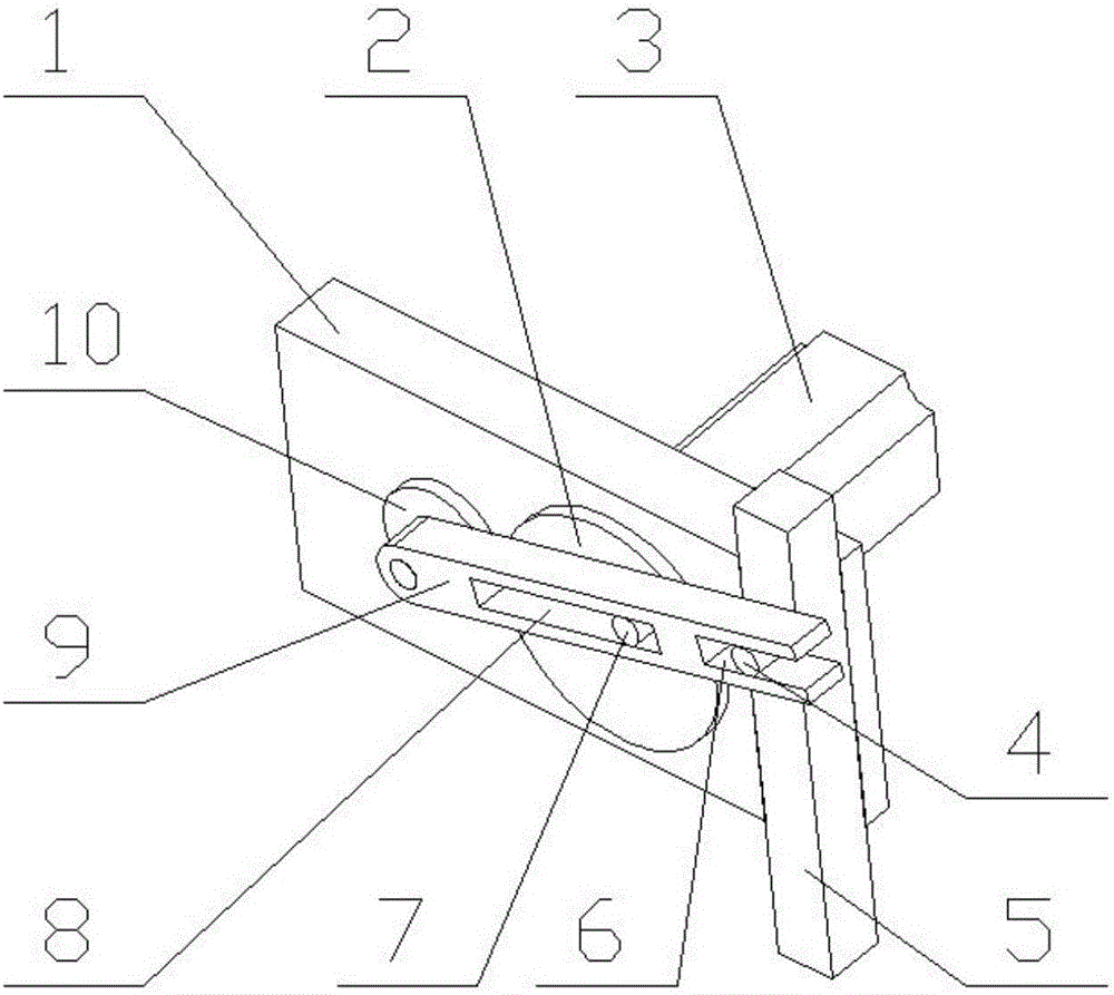
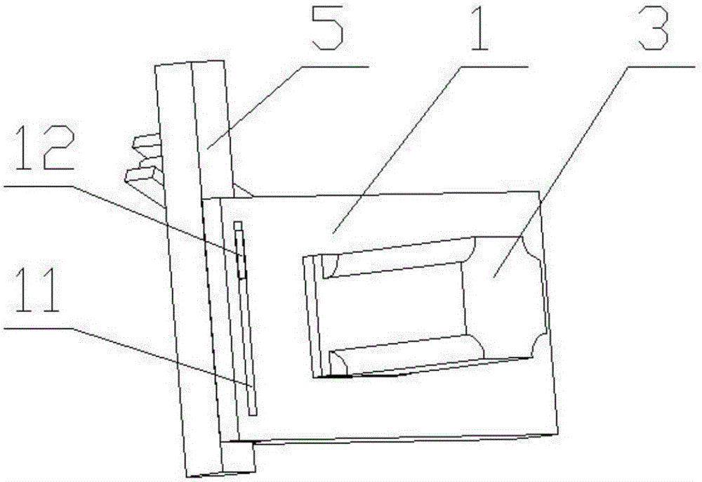
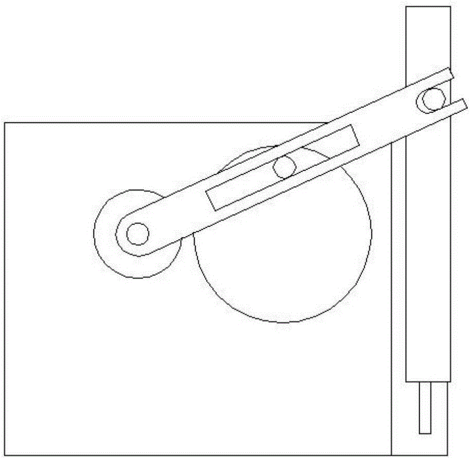
[0048] like figure 1 As shown, a three-axis robot arm includes a main frame 1, a servo motor 3 and a lifting arm 5 arranged at the end of the main frame 1, such as figure 2 As shown, the end of the main frame 1 is provided with a third chute 11, the length of the third chute 11 is L=100mm, the middle part is provided with a runner 2 and a lifting arm 9; the lifting arm 5 is provided with a second protrusion 12; the second protrusion 12 is set in the third chute 11; one end of the lifting arm 9 and the center of the runner 2 are connected to the main frame 1 through the pin shaft; the lifting arm 9 and the runner 2 can be wound around the pin shaft Rotate relative to the main frame 1; the axis of the pin shaft at one end of the lifting arm 9, the center line of the runner 2 and the surface of the main frame 1 intersect to form two points The connection line is perpendicular to the straight line where the chute is located; the runner 2 is provided with The eccentric column 7; th...

Embodiment 2

[0063] A three-axis robot arm, the same as Embodiment 1, the difference is that a rotating base plate 10 is provided at the joint between the pulling arm 9 and the runner 2; the rotating base plate 10 is fixedly connected with the running wheel 2; the pulling arm 9 One end of the pin shaft connected with the running wheel 2 is fixedly connected with the running wheel 2, and the other end passes through the lifting arm 9 so that the lifting arm 9 can rotate around the pin shaft.

[0064] This embodiment can have the same beneficial effect as that of Embodiment 1.


PUM


Abstract

The invention discloses a three-axis robot and an arm and using method thereof and belongs to the field of robots. By the adoption of the three-axis robot and the arm and using method thereof, the problems that an existing assembling and transferring robot is complex in structure, large in size and high in manufacturing cost are solved. The arm comprises a main frame, a servo motor and a lifting arm arranged at the end of the main frame. A sliding groove is formed in the end of the main frame. A turning wheel and a pulling-up arm are arranged in the middle of the main frame. The lifting arm is arranged in the sliding groove. One end of the pulling-up arm and the center of the turning wheel are both connected with the main frame through a hinge pin. The pulling-up arm and the turning wheel can rotate relative to the main frame around the hinge pin. An eccentric column is arranged on the turning wheel. A first sliding groove is formed in the end of the pulling-up arm, and a second sliding groove is formed in the middle of the pulling-up arm. The eccentric column is arranged in the second sliding groove. The lifting arm is provided with a first protrusion, and the first protrusion is arranged in the first sliding groove. The servo motor is fixedly connected with the hinge pin at the center of the turning wheel. The three-axis robot can replace the existing assembling and transferring robot which is complex in structure to achieve the effects of improving the production efficiency and reducing the production cost.

Description

technical field [0001] The invention belongs to the field of robots, and in particular relates to a three-axis robot, an arm thereof and a use method thereof. Background technique [0002] Most of the robots currently on the market for electronic assembly and fast food transfer on the production line are SCARA robots and spider-handed robots, which can quickly transfer items and position them accurately. However, these robots have complex structures and high production costs, and the same action often needs to be completed by four-axis or even six-axis mechanisms. [0003] Chinese patent application number 201420515514.6, the patent document published on April 15, 2015, discloses a SCARA-type mechanical arm, which includes a base, a power part and a rotating part, and the power parts are all fixedly arranged on In the base, the power part can drive the rotating part to rotate at any angle and position at any orientation. The SCARA-type mechanical arm described in this util...

Claims


Application Information

Patent Timeline
IPC IPC(8): B25J9/04B25J18/02
CPCB25J9/041B25J18/025
Inventor 高大宏俞能超吴德寒
Owner 马鞍山工蜂智能科技有限公司
Why Eureka
Try Eureka