Bucket type elevating ship loader

A bucket elevator and ship loader technology, which is applied in the directions of transportation, packaging, loading/unloading, etc., can solve the problems of poor sealing performance, long occupied track length, complicated installation, etc., and achieve good sealing performance, easy sealing, and shortened The effect of the itinerary

Active Publication Date: 2016-10-26
HENAN CRANE
View PDF8 Cites 10 Cited by
  • Summary
  • Abstract
  • Description
  • Claims
  • Application Information

AI Technical Summary

Problems solved by technology

[0002] The ship loader is a new type, high-efficiency, environmental protection, energy-saving continuous bulk material transportation machinery. The current domestic use of the tail car is mostly used when feeding the ship loader. The tail car of the ship loader and the rear conveyor belt conveyor system During the loading operation, the material is transferred from the rear conveying system to the belt conveyor on the tail car of the ship loader, and then sent to the front section of the boom, and loaded into the cabin through the chute, through the pitching, turning, sliding of the boom The expansion and contraction of the barrel and the walking of the whole machine change the position of the loading point to adapt to the size requirements of the cabin and the change of the water level. This kind of tail car feeding method has many steel structures, and the installation is more complicated and occupies a longer track length. Long, the number of ship loaders that can be installed on the same wharf is small, and the sealing performance is poor, so it cannot meet the requirements of not affecting the surrounding environment during the transportation of materials

Method used


Image

  • Bucket type elevating ship loader
  • Bucket type elevating ship loader
  • Bucket type elevating ship loader

Examples


Embodiment Construction

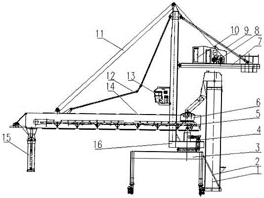
[0012] This technical solution is suitable for the working conditions where the wharf track is short, the material particles are small, and dust is likely to be generated at the material transfer point during transportation. It can meet the bucket elevator type ship loader installed in multiple places in the wharf according to the unloading situation. Specific examples figure 1 As shown, the hoist is connected with the upstream conveying belt conveyor system, and the material is transferred from the upstream to the hoist. The hoist is fixed on the platform support by high-strength bolts and connected with the door frame 3 by a pull rod 2. There are at least four pull rods to ensure the stability of the hoist. When working, the hoist can move with the cart traveling mechanism installed on the lower part of the mast. The other end of the material barrel is inserted into the funnel 14, and a slewing support 4 is installed on the upper part of the door frame. The slewing support i...


PUM


Abstract

The invention discloses a bucket type elevating ship loader. An elevator is connected with an upstream conveying belt conveyor system; materials are conveyed and transferred to the elevator from the upstream; the elevator is fixed to a platform support through high-strength bolts and connected with a portal through pulling rods; the portal is mainly composed of a main beam, supporting legs, a large trolley mechanism, the platform support, the pulling rods and an elevator pulling rod; a large trolley walking mechanism is connected with the supporting legs of the main beam through bolts and flanges; the position of an outlet in the upper portion of the elevator is in but joint with a material falling barrel; the other end of the material falling barrel is inserted into a funnel; a rotating support is installed on the upper portion of the portal and connected with a flange on the lower portion of a stand column rotating table and a flange on the upper portion of the portal through bolts; a cab is installed on the stand column rotating table; an upper rotating table is hinged to the upper portion of the stand column rotating table and is sequentially provided with a pitching mechanism and an electrical room; a cantilever crane is installed on the upper portion of a rotating mechanism and is internally provided with a conveying belt conveyor; and a chute tube is installed on the head portion of the cantilever crane.

Description

technical field [0001] The invention relates to a bucket-type elevating ship loader, which is particularly suitable for use on wharfs with short wharf tracks and good sealing performance required during material transportation. Background technique [0002] The ship loader is a new type, high-efficiency, environmental protection, energy-saving continuous bulk material transportation machinery. The current domestic use of the tail car is mostly used when feeding the ship loader. The tail car of the ship loader and the rear conveyor belt conveyor system During the loading operation, the material is transferred from the rear conveying system to the belt conveyor on the tail car of the ship loader, and then sent to the front section of the boom, and loaded into the cabin through the chute, through the pitching, turning, sliding of the boom The expansion and contraction of the barrel and the walking of the whole machine change the position of the loading point to adapt to the s...

Claims


Application Information

Patent Timeline
Patent Type & Authority Applications(China)
IPC IPC(8): B65G67/60
CPCB65G67/606
Inventor 王龙李波陈蕊娄苹苹付仁辉朱瑸张正传李鹏伟
Owner HENAN CRANE
Why Eureka
Try Eureka